

11.3.5.3 Design of Valve Distribution Path
(1) Valve distribution area
Valve distribution area refers to the area of working air flowing through each
passage. The ratio of air pavement area to cylinder working area is called the ratio
of valve distribution area. If the ratio of valve distribution area is expressed by K,
then there is
K ¼
A
A h
or A ¼ KA h
ð11:27Þ
where
A Required valve distribution area;
A h Corresponding piston working area.
The velocity of gas flow can be calculated according to the following equation:
v ¼
Qc 0
60Ac p
ð11:28Þ
where
Q Air consumption of impactor equipment;
c 0 Air gravity at an absolute atmospheric pressure, c 0 ¼ 12:25 N=m
3 ;
c p Air gravity of working gas (absolute pressure);
A Valve distribution area.
The reasonable flow velocity of gas in the pipeline is generally 30 $ 70 m=s, the
clearance flow velocity in the valve is not more than 60 $ 70 m=s, the airflow
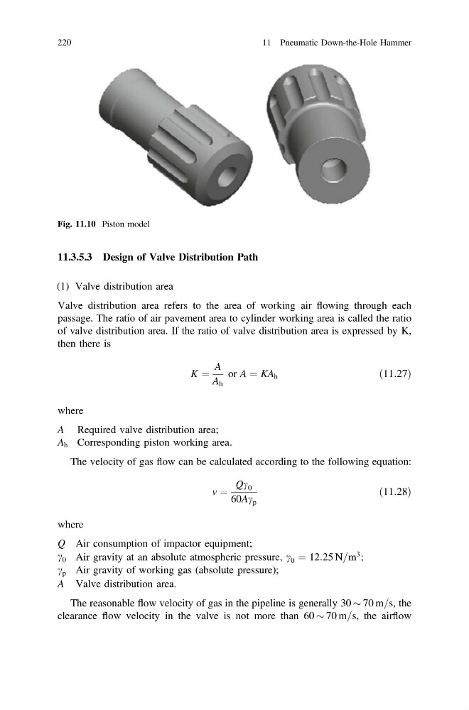
Fig. 11.10 Piston model
220
11 Pneumatic Down-the-Hole Hammer
(1) Valve distribution area
Valve distribution area refers to the area of working air flowing through each
passage. The ratio of air pavement area to cylinder working area is called the ratio
of valve distribution area. If the ratio of valve distribution area is expressed by K,
then there is
K ¼
A
A h
or A ¼ KA h
ð11:27Þ
where
A Required valve distribution area;
A h Corresponding piston working area.
The velocity of gas flow can be calculated according to the following equation:
v ¼
Qc 0
60Ac p
ð11:28Þ
where
Q Air consumption of impactor equipment;
c 0 Air gravity at an absolute atmospheric pressure, c 0 ¼ 12:25 N=m
3 ;
c p Air gravity of working gas (absolute pressure);
A Valve distribution area.
The reasonable flow velocity of gas in the pipeline is generally 30 $ 70 m=s, the
clearance flow velocity in the valve is not more than 60 $ 70 m=s, the airflow
Fig. 11.10 Piston model
220
11 Pneumatic Down-the-Hole Hammer