

stage. When the upper end face of piston 6 passes through the lower end face of
valve seat 3, the back chamber is closed and compressed, the front chamber is
intake, and the piston 6 accelerates upward. This process is the second stage. When
piston 6 moves to the intake passage of front chamber are blocked, the front and
back chambers are closed, but the pressure of the front chamber is greater than that
of the back chamber, and the piston still accelerates upward, which is the third
stage. The piston 6 continues to move upward, opening the inlet passage of the rear
chamber, and the gas enters the rear chamber. At this time, the pressure of the rear
chamber exceeds the pressure of the front chamber. The piston moves from upward
acceleration to upward deceleration, but the speed does not decrease to zero. This
process is the fourth stage. When the lower end of piston passes over the upper end
of exhaust valve 7, the lower chamber exhausts and the upper chamber still intakes.
The piston continues to decelerate until the speed decreases to zero. This process is
the fifth stage. These five stages constitute the return motion of the piston 6, after
which the piston 6 will move downward. The sequence of five stages is the same as
the ascending process, but the sequence is opposite. Finally, piston 6 impacts
drilling bit 9 to produce impact energy. Figure 11.14 shows five cycle diagrams of
single cycle return of pneumatic DTH hammer. Figure 11.15 shows the valve
distribution status of the front and rear chamber of DTH hammer. The origin of the
coordinates is the upper end of the piston impact drill. The X-axis is the axis of the
cylinder block. X t
ð Þ represents the displacement of the piston with time. The piston
first makes a return motion, during which the front chamber experiences intake
stroke (L 4 ), expansion stroke (L 2 À L 4 ) and exhaust stroke (L max À L 2 ). The rear
Upper joint
Shim
Clamp
spring
Spiral casing
Check valve
Spring Valve
seat
Inner
cylinder
Piston
Harfur block
Lower joint
Drilling bit
Shim
Exhaust valve
Bushing
Outer cylinder
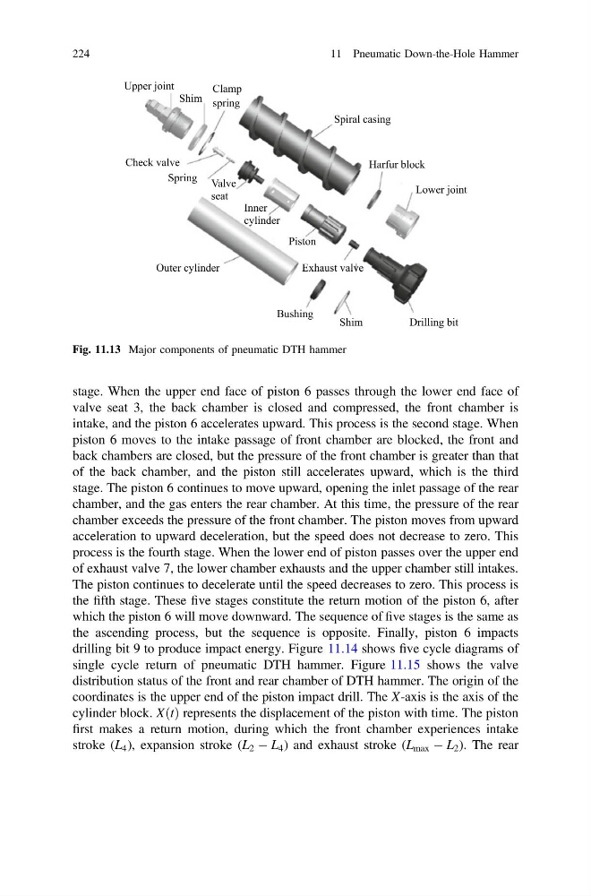
Fig. 11.13 Major components of pneumatic DTH hammer
224
11 Pneumatic Down-the-Hole Hammer
valve seat 3, the back chamber is closed and compressed, the front chamber is
intake, and the piston 6 accelerates upward. This process is the second stage. When
piston 6 moves to the intake passage of front chamber are blocked, the front and
back chambers are closed, but the pressure of the front chamber is greater than that
of the back chamber, and the piston still accelerates upward, which is the third
stage. The piston 6 continues to move upward, opening the inlet passage of the rear
chamber, and the gas enters the rear chamber. At this time, the pressure of the rear
chamber exceeds the pressure of the front chamber. The piston moves from upward
acceleration to upward deceleration, but the speed does not decrease to zero. This
process is the fourth stage. When the lower end of piston passes over the upper end
of exhaust valve 7, the lower chamber exhausts and the upper chamber still intakes.
The piston continues to decelerate until the speed decreases to zero. This process is
the fifth stage. These five stages constitute the return motion of the piston 6, after
which the piston 6 will move downward. The sequence of five stages is the same as
the ascending process, but the sequence is opposite. Finally, piston 6 impacts
drilling bit 9 to produce impact energy. Figure 11.14 shows five cycle diagrams of
single cycle return of pneumatic DTH hammer. Figure 11.15 shows the valve
distribution status of the front and rear chamber of DTH hammer. The origin of the
coordinates is the upper end of the piston impact drill. The X-axis is the axis of the
cylinder block. X t
ð Þ represents the displacement of the piston with time. The piston
first makes a return motion, during which the front chamber experiences intake
stroke (L 4 ), expansion stroke (L 2 À L 4 ) and exhaust stroke (L max À L 2 ). The rear
Upper joint
Shim
Clamp
spring
Spiral casing
Check valve
Spring Valve
seat
Inner
cylinder
Piston
Harfur block
Lower joint
Drilling bit
Shim
Exhaust valve
Bushing
Outer cylinder
Fig. 11.13 Major components of pneumatic DTH hammer
224
11 Pneumatic Down-the-Hole Hammer