

consumption, and reduce the volume and mass of the system structure and
components as much as possible.
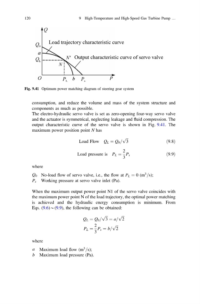
The electro-hydraulic servo valve is set as zero-opening four-way servo valve
and the actuator is symmetrical, neglecting leakage and fluid compression. The
output characteristic curve of the servo valve is shown in Fig. 9.41. The
maximum power position point N has
Load Flow Q L ¼ Q 0 =
ffiffi ffi
3
p
ð9:8Þ
Load pressure is P L ¼
2
3
P s
ð9:9Þ
where
Q 0 No-load flow of servo valve, i.e., the flow at P L ¼ 0 (m
3
=s);
P s Working pressure at servo valve inlet (Pa).
When the maximum output power point N1 of the servo valve coincides with
the maximum power point N of the load trajectory, the optimal power matching
is achieved and the hydraulic energy consumption is minimum. From
Eqs. (9.6)*(9.9), the following can be obtained:
Q L ¼ Q 0 =
ffiffi ffi
3
p ¼ a=
ffiffi ffi
2
p
P L ¼
2
3
P s ¼ b=
ffiffi ffi
2
p
where
a Maximum load flow (m
3
=s);
b Maximum load pressure (Pa).
Load trajectory characteristic curve
Output characteristic curve of servo valve
Fig. 9.41 Optimum power matching diagram of steering gear system
120
9 High-Temperature and High-Speed Gas Turbine Pump …
components as much as possible.
The electro-hydraulic servo valve is set as zero-opening four-way servo valve
and the actuator is symmetrical, neglecting leakage and fluid compression. The
output characteristic curve of the servo valve is shown in Fig. 9.41. The
maximum power position point N has
Load Flow Q L ¼ Q 0 =
ffiffi ffi
3
p
ð9:8Þ
Load pressure is P L ¼
2
3
P s
ð9:9Þ
where
Q 0 No-load flow of servo valve, i.e., the flow at P L ¼ 0 (m
3
=s);
P s Working pressure at servo valve inlet (Pa).
When the maximum output power point N1 of the servo valve coincides with
the maximum power point N of the load trajectory, the optimal power matching
is achieved and the hydraulic energy consumption is minimum. From
Eqs. (9.6)*(9.9), the following can be obtained:
Q L ¼ Q 0 =
ffiffi ffi
3
p ¼ a=
ffiffi ffi
2
p
P L ¼
2
3
P s ¼ b=
ffiffi ffi
2
p
where
a Maximum load flow (m
3
=s);
b Maximum load pressure (Pa).
Load trajectory characteristic curve
Output characteristic curve of servo valve
Fig. 9.41 Optimum power matching diagram of steering gear system
120
9 High-Temperature and High-Speed Gas Turbine Pump …