

There is dN=dt ¼ 0 at the maximum output power point, and tan xt ¼ 1 is
obtained. At this time, sin xt ¼ cos xt ¼ 1=
ffiffi ffi
2
p
, then
_
Y ¼ _
Y max =
ffiffi ffi
2
p
ð9:7Þ
N max ¼
1
2
Rx ÀmRx
2
þ KR
À
Á ¼ F max _
Y max =2
9.2.1.3 Load Trajectory Characteristics
(1) From Fig. 9.35, it can be seen that the load speed and load force are sinusoidal
curves with the same frequency and 90
phase difference. The maximum load
force and maximum load speed do not occur at the same time, but differ by a
quarter of the motion cycle.
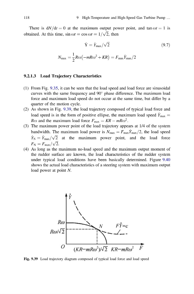
(2) As shown in Fig. 9.39, the load trajectory composed of typical load force and
load speed is in the form of positive ellipse, the maximum load speed _
Y max ¼
Rx and the maximum load force F max ¼ KR À mRx
2 .
(3) The maximum power point of the load trajectory appears at 1/4 of the system
bandwidth. The maximum load power is N max ¼ F max _
Y max =2, the load speed
_
Y N ¼ _
Y max =
ffiffi ffi
2
p
at the maximum power point, and the load force
F N ¼ F max =
ffiffi ffi
2
p
.
(4) As long as the maximum no-load speed and the maximum output moment of
the rudder surface are known, the load characteristics of the rudder system
under typical load conditions have been basically determined. Figure 9.40
shows the actual load characteristics of a steering system with maximum output
load power at point N.
Fig. 9.39 Load trajectory diagram composed of typical load force and load speed
118
9 High-Temperature and High-Speed Gas Turbine Pump …
obtained. At this time, sin xt ¼ cos xt ¼ 1=
ffiffi ffi
2
p
, then
_
Y ¼ _
Y max =
ffiffi ffi
2
p
ð9:7Þ
N max ¼
1
2
Rx ÀmRx
2
þ KR
À
Á ¼ F max _
Y max =2
9.2.1.3 Load Trajectory Characteristics
(1) From Fig. 9.35, it can be seen that the load speed and load force are sinusoidal
curves with the same frequency and 90
phase difference. The maximum load
force and maximum load speed do not occur at the same time, but differ by a
quarter of the motion cycle.
(2) As shown in Fig. 9.39, the load trajectory composed of typical load force and
load speed is in the form of positive ellipse, the maximum load speed _
Y max ¼
Rx and the maximum load force F max ¼ KR À mRx
2 .
(3) The maximum power point of the load trajectory appears at 1/4 of the system
bandwidth. The maximum load power is N max ¼ F max _
Y max =2, the load speed
_
Y N ¼ _
Y max =
ffiffi ffi
2
p
at the maximum power point, and the load force
F N ¼ F max =
ffiffi ffi
2
p
.
(4) As long as the maximum no-load speed and the maximum output moment of
the rudder surface are known, the load characteristics of the rudder system
under typical load conditions have been basically determined. Figure 9.40
shows the actual load characteristics of a steering system with maximum output
load power at point N.
Fig. 9.39 Load trajectory diagram composed of typical load force and load speed
118
9 High-Temperature and High-Speed Gas Turbine Pump …