

Thermal
engine
Battery
Generator
DC/DC
Converter
Traction
drive
Driven wheels
Transmission
Fuel Cells
347
The drivetrain of a vehicle basically comprises the flow of power from the
source to the ultimate sink, where it is used. A typical hybrid fuel-cell based
drivetrain is shown in Figure 1 1.6.
In the case of direct hydrogen FCV, the output voltage from each cell is collected and sent to the power electronic converter stage, where it is converted
to usable power by using a DC/DC converter. This power is then supplied to
the motor based on the optimized control strategy. The power control unit
processes acceleration commands of the driver and produces the necessary
power for specific operation of the FCS.
In HEVs, there are two popular topologies. The first is the series hybrid
configuration and the second option is the parallel hybrid topology. The difference between the two is presented schematically in Figures 1 1.7 and 11.8.
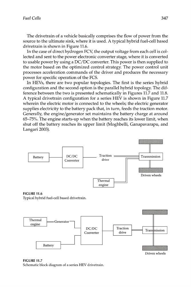
A typical drivetrain configuration for a series HEV is shown in Figure 1 1.7
wherein the electric motor is connected to the wheels; the electric generator
supplies electricity to the battery pack that, in turn, feeds the traction motor.
Generally, the engine/generator set maintains the battery charge at around
65–75%. The engine starts-up when the battery reaches its lower limit, when
shut off the battery reaches its upper limit (Moghbelli, Ganapavarapu, and
Langari 2003).
Transmission
Driven wheels
Thermal
engine
Traction
drive
DC/DC
Converter
Battery
Figure 11.6
Typical hybrid fuel-cell based drivetrain.
Figure 11.7
Schematic block diagram of a series HEV drivetrain.
engine
Battery
Generator
DC/DC
Converter
Traction
drive
Driven wheels
Transmission
Fuel Cells
347
The drivetrain of a vehicle basically comprises the flow of power from the
source to the ultimate sink, where it is used. A typical hybrid fuel-cell based
drivetrain is shown in Figure 1 1.6.
In the case of direct hydrogen FCV, the output voltage from each cell is collected and sent to the power electronic converter stage, where it is converted
to usable power by using a DC/DC converter. This power is then supplied to
the motor based on the optimized control strategy. The power control unit
processes acceleration commands of the driver and produces the necessary
power for specific operation of the FCS.
In HEVs, there are two popular topologies. The first is the series hybrid
configuration and the second option is the parallel hybrid topology. The difference between the two is presented schematically in Figures 1 1.7 and 11.8.
A typical drivetrain configuration for a series HEV is shown in Figure 1 1.7
wherein the electric motor is connected to the wheels; the electric generator
supplies electricity to the battery pack that, in turn, feeds the traction motor.
Generally, the engine/generator set maintains the battery charge at around
65–75%. The engine starts-up when the battery reaches its lower limit, when
shut off the battery reaches its upper limit (Moghbelli, Ganapavarapu, and
Langari 2003).
Transmission
Driven wheels
Thermal
engine
Traction
drive
DC/DC
Converter
Battery
Figure 11.6
Typical hybrid fuel-cell based drivetrain.
Figure 11.7
Schematic block diagram of a series HEV drivetrain.