

346
Alternative Fuels for Transportation
Driver
motor
Driven wheels
Fuel cell auxiliary power unit
Controller
Ventilation
fan
Fuel supply
Cooling
Air supply
system
system
system
Nontraction
electrical
loads
Transmission
M
DC/AC
Electric
traction
T, w
commands
Vehicle
controller
DC/DC
converter
DC/DC
converter
inverter
discharge unit
Battery charge/
Battery
Fuel
cell
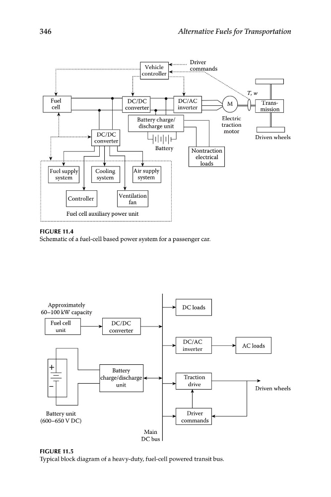
Figure 11.4
Schematic of a fuel-cell based power system for a passenger car.
Approximately
60–100 kW capacity
Fuel cell
unit
DC/DC
converter
Battery
charge/discharge
unit
Traction
drive
Driver
commands
DC loads
DC/AC
inverter
AC loads
Main
DC bus
Driven wheels
Battery unit
(600–650 V DC)
Figure 11.5
Typical block diagram of a heavy-duty, fuel-cell powered transit bus.
Alternative Fuels for Transportation
Driver
motor
Driven wheels
Fuel cell auxiliary power unit
Controller
Ventilation
fan
Fuel supply
Cooling
Air supply
system
system
system
Nontraction
electrical
loads
Transmission
M
DC/AC
Electric
traction
T, w
commands
Vehicle
controller
DC/DC
converter
DC/DC
converter
inverter
discharge unit
Battery charge/
Battery
Fuel
cell
Figure 11.4
Schematic of a fuel-cell based power system for a passenger car.
Approximately
60–100 kW capacity
Fuel cell
unit
DC/DC
converter
Battery
charge/discharge
unit
Traction
drive
Driver
commands
DC loads
DC/AC
inverter
AC loads
Main
DC bus
Driven wheels
Battery unit
(600–650 V DC)
Figure 11.5
Typical block diagram of a heavy-duty, fuel-cell powered transit bus.