

S
Atmosphere
Air compressor/
expander
Fuel cell stack
: Water separator
* Cooling and heat generation circuits for fuel processor are not included.
** Secondary coolant circuit is not included.
: Pump
M
Air supply
PROX
Liquid fuel supply
Fuel processor*
Vaporizer
**
Hydrogen supply
Hydrogen tank
Lq. fuel
tank
Water return
Water supply
Steam
reformer
Water supply
Hydrogen-rich
gas supply
Heat
source
Deionized
water tank
Air return
: Pressure regulator valve
: Solenoid control valve
: Ejector
: Humidifier
: Heat exchanger
S
S
Fuel Cells
329
as metals. Various methods and techniques must be developed to combat
metallic corrosion and eliminate the passive layer that causes unacceptable
reduction in contact resistance and possible fouling of the catalyst and the
ionomer (Tawfik, Hung, and Mahajan 2007). The schematic of a simplified
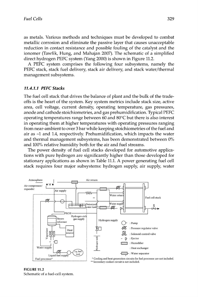
direct hydrogen PEFC system (Yang 2000) is shown in Figure 11.2.
A PEFC system comprises the following four subsystems, namely the
PEFC stack, stack fuel delivery, stack air delivery, and stack water/thermal
management subsystems.
11.4.1.1 PEFC Stacks
The fuel cell stack that drives the balance of plant and the bulk of the tradeoffs is the heart of the system. Key system metrics include stack size, active
area, cell voltage, current density, operating temperature, gas pressures,
anode and cathode stoichiometries, and gas prehumidification. Typical PEFC
operating temperatures range between 60 and 80°C but there is also interest
in operating them at higher temperatures with operating pressures ranging
from near-ambient to over 3 bar while keeping stoichiometries of the fuel and
air as ~1 and 1.4, respectively. Prehumidification, which impacts the water
and thermal management subsystems, has been demonstrated between 0%
and 100% relative humidity both for the air and fuel streams.
The power density of fuel cell stacks developed for automotive applications with pure hydrogen are significantly higher than those developed for
stationary applications as shown in Table 11.1. A power generating fuel cell
stack requires four major subsystems: hydrogen supply, air supply, water
Figure 11.2
Schematic of a fuel-cell system.
Atmosphere
Air compressor/
expander
Fuel cell stack
: Water separator
* Cooling and heat generation circuits for fuel processor are not included.
** Secondary coolant circuit is not included.
: Pump
M
Air supply
PROX
Liquid fuel supply
Fuel processor*
Vaporizer
**
Hydrogen supply
Hydrogen tank
Lq. fuel
tank
Water return
Water supply
Steam
reformer
Water supply
Hydrogen-rich
gas supply
Heat
source
Deionized
water tank
Air return
: Pressure regulator valve
: Solenoid control valve
: Ejector
: Humidifier
: Heat exchanger
S
S
Fuel Cells
329
as metals. Various methods and techniques must be developed to combat
metallic corrosion and eliminate the passive layer that causes unacceptable
reduction in contact resistance and possible fouling of the catalyst and the
ionomer (Tawfik, Hung, and Mahajan 2007). The schematic of a simplified
direct hydrogen PEFC system (Yang 2000) is shown in Figure 11.2.
A PEFC system comprises the following four subsystems, namely the
PEFC stack, stack fuel delivery, stack air delivery, and stack water/thermal
management subsystems.
11.4.1.1 PEFC Stacks
The fuel cell stack that drives the balance of plant and the bulk of the tradeoffs is the heart of the system. Key system metrics include stack size, active
area, cell voltage, current density, operating temperature, gas pressures,
anode and cathode stoichiometries, and gas prehumidification. Typical PEFC
operating temperatures range between 60 and 80°C but there is also interest
in operating them at higher temperatures with operating pressures ranging
from near-ambient to over 3 bar while keeping stoichiometries of the fuel and
air as ~1 and 1.4, respectively. Prehumidification, which impacts the water
and thermal management subsystems, has been demonstrated between 0%
and 100% relative humidity both for the air and fuel streams.
The power density of fuel cell stacks developed for automotive applications with pure hydrogen are significantly higher than those developed for
stationary applications as shown in Table 11.1. A power generating fuel cell
stack requires four major subsystems: hydrogen supply, air supply, water
Figure 11.2
Schematic of a fuel-cell system.