

330
Alternative Fuels for Transportation
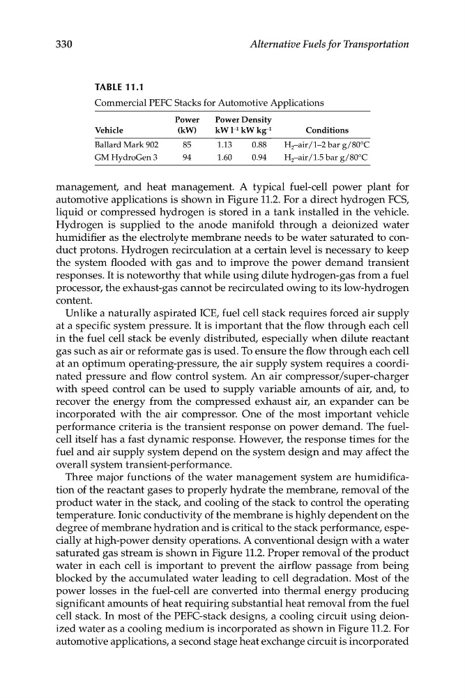
TABLe 11.1
Commercial PEFC Stacks for Automotive Applications
Power
Power Density
Vehicle
(kW)
kW l –1 kW kg –1
Conditions
Ballard Mark 902
85
1.13
0.88
H 2 –air/1–2 bar g/80°C
GM HydroGen 3
94
1.60
0.94
H 2 –air/1.5 bar g/80°C
management, and heat management. A typical fuel-cell power plant for
automotive applications is shown in Figure 11.2. For a direct hydrogen FCS,
liquid or compressed hydrogen is stored in a tank installed in the vehicle.
Hydrogen is supplied to the anode manifold through a deionized water
humidifier as the electrolyte membrane needs to be water saturated to conduct protons. Hydrogen recirculation at a certain level is necessary to keep
the system flooded with gas and to improve the power demand transient
responses. It is noteworthy that while using dilute hydrogen-gas from a fuel
processor, the exhaust-gas cannot be recirculated owing to its low-hydrogen
content.
Unlike a naturally aspirated ICE, fuel cell stack requires forced air supply
at a specific system pressure. It is important that the flow through each cell
in the fuel cell stack be evenly distributed, especially when dilute reactant
gas such as air or reformate gas is used. To ensure the flow through each cell
at an optimum operating-pressure, the air supply system requires a coordinated pressure and flow control system. An air compressor/super-charger
with speed control can be used to supply variable amounts of air, and, to
recover the energy from the compressed exhaust air, an expander can be
incorporated with the air compressor. One of the most important vehicle
performance criteria is the transient response on power demand. The fuelcell itself has a fast dynamic response. However, the response times for the
fuel and air supply system depend on the system design and may affect the
overall system transient-performance.
Three major functions of the water management system are humidification of the reactant gases to properly hydrate the membrane, removal of the
product water in the stack, and cooling of the stack to control the operating
temperature. Ionic conductivity of the membrane is highly dependent on the
degree of membrane hydration and is critical to the stack performance, especially at high-power density operations. A conventional design with a water
saturated gas stream is shown in Figure 11.2. Proper removal of the product
water in each cell is important to prevent the airflow passage from being
blocked by the accumulated water leading to cell degradation. Most of the
power losses in the fuel-cell are converted into thermal energy producing
significant amounts of heat requiring substantial heat removal from the fuel
cell stack. In most of the PEFC-stack designs, a cooling circuit using deionized water as a cooling medium is incorporated as shown in Figure 11.2. For
automotive applications, a second stage heat exchange circuit is incorporated
Alternative Fuels for Transportation
TABLe 11.1
Commercial PEFC Stacks for Automotive Applications
Power
Power Density
Vehicle
(kW)
kW l –1 kW kg –1
Conditions
Ballard Mark 902
85
1.13
0.88
H 2 –air/1–2 bar g/80°C
GM HydroGen 3
94
1.60
0.94
H 2 –air/1.5 bar g/80°C
management, and heat management. A typical fuel-cell power plant for
automotive applications is shown in Figure 11.2. For a direct hydrogen FCS,
liquid or compressed hydrogen is stored in a tank installed in the vehicle.
Hydrogen is supplied to the anode manifold through a deionized water
humidifier as the electrolyte membrane needs to be water saturated to conduct protons. Hydrogen recirculation at a certain level is necessary to keep
the system flooded with gas and to improve the power demand transient
responses. It is noteworthy that while using dilute hydrogen-gas from a fuel
processor, the exhaust-gas cannot be recirculated owing to its low-hydrogen
content.
Unlike a naturally aspirated ICE, fuel cell stack requires forced air supply
at a specific system pressure. It is important that the flow through each cell
in the fuel cell stack be evenly distributed, especially when dilute reactant
gas such as air or reformate gas is used. To ensure the flow through each cell
at an optimum operating-pressure, the air supply system requires a coordinated pressure and flow control system. An air compressor/super-charger
with speed control can be used to supply variable amounts of air, and, to
recover the energy from the compressed exhaust air, an expander can be
incorporated with the air compressor. One of the most important vehicle
performance criteria is the transient response on power demand. The fuelcell itself has a fast dynamic response. However, the response times for the
fuel and air supply system depend on the system design and may affect the
overall system transient-performance.
Three major functions of the water management system are humidification of the reactant gases to properly hydrate the membrane, removal of the
product water in the stack, and cooling of the stack to control the operating
temperature. Ionic conductivity of the membrane is highly dependent on the
degree of membrane hydration and is critical to the stack performance, especially at high-power density operations. A conventional design with a water
saturated gas stream is shown in Figure 11.2. Proper removal of the product
water in each cell is important to prevent the airflow passage from being
blocked by the accumulated water leading to cell degradation. Most of the
power losses in the fuel-cell are converted into thermal energy producing
significant amounts of heat requiring substantial heat removal from the fuel
cell stack. In most of the PEFC-stack designs, a cooling circuit using deionized water as a cooling medium is incorporated as shown in Figure 11.2. For
automotive applications, a second stage heat exchange circuit is incorporated