

70
Q. Liu et al.
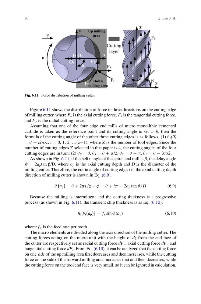
Fig. 6.11 Force distribution of milling cutter
Figure 6.11 shows the distribution of force in three directions on the cutting edge
of milling cutter, where F a is the axial cutting force, F t is the tangential cutting force,
and F r is the radial cutting force.
Assuming that one of the four edge end mills of micro monolithic cemented
carbide is taken as the reference point and its cutting angle is set as θ, then the
formula of the cutting angle of the other three cutting edges is as follows: (1) θ i (0)
= θ + i2π /z, i = 0, 1, 2, …(z−1), where Z is the number of tool edges. Since the
number of cutting edges Z selected in this paper is 4, the cutting angles of the four
cutting edges are in turn: (2) θ 0 = θ, θ 1 = θ + π/2, θ 2 = θ + π, θ 3 = θ + 3π/2.
As shown in Fig. 6.11, if the helix angle of the spiral end mill is β, the delay angle
ψ = 2a p tan β/D, where a p is the axial cutting depth and D is the diameter of the
milling cutter. Therefore, the cut in angle of cutting edge i in the axial cutting depth
direction of milling cutter is shown in Eq. (6.9).
θ i
a p
= θ + 2πi/z − φ = θ + iπ − 2a p tan β/D
(6.9)
Because the milling is intermittent and the cutting thickness is a progressive
process (as shown in Fig. 6.11), the transient chip thickness is as Eq. (6.10):
h i [θ i
a p
] = f z sin θ i (a p )
(6.10)
where: f z is the feed rate per tooth.
The micro elements are divided along the axis direction of the milling cutter. The
cutting forces acting on the micro unit with the height of dz from the end face of
the cutter are respectively set as radial cutting force dF r , axial cutting force dF a and
tangential cutting force dF t . From Eq. (6.10), it can be analyzed that the cutting force
on one side of the up milling area first decreases and then increases, while the cutting
force on the side of the forward milling area increases first and then decreases, while
the cutting force on the tool end face is very small, so it can be ignored in calculation.
Q. Liu et al.
Fig. 6.11 Force distribution of milling cutter
Figure 6.11 shows the distribution of force in three directions on the cutting edge
of milling cutter, where F a is the axial cutting force, F t is the tangential cutting force,
and F r is the radial cutting force.
Assuming that one of the four edge end mills of micro monolithic cemented
carbide is taken as the reference point and its cutting angle is set as θ, then the
formula of the cutting angle of the other three cutting edges is as follows: (1) θ i (0)
= θ + i2π /z, i = 0, 1, 2, …(z−1), where Z is the number of tool edges. Since the
number of cutting edges Z selected in this paper is 4, the cutting angles of the four
cutting edges are in turn: (2) θ 0 = θ, θ 1 = θ + π/2, θ 2 = θ + π, θ 3 = θ + 3π/2.
As shown in Fig. 6.11, if the helix angle of the spiral end mill is β, the delay angle
ψ = 2a p tan β/D, where a p is the axial cutting depth and D is the diameter of the
milling cutter. Therefore, the cut in angle of cutting edge i in the axial cutting depth
direction of milling cutter is shown in Eq. (6.9).
θ i
a p
= θ + 2πi/z − φ = θ + iπ − 2a p tan β/D
(6.9)
Because the milling is intermittent and the cutting thickness is a progressive
process (as shown in Fig. 6.11), the transient chip thickness is as Eq. (6.10):
h i [θ i
a p
] = f z sin θ i (a p )
(6.10)
where: f z is the feed rate per tooth.
The micro elements are divided along the axis direction of the milling cutter. The
cutting forces acting on the micro unit with the height of dz from the end face of
the cutter are respectively set as radial cutting force dF r , axial cutting force dF a and
tangential cutting force dF t . From Eq. (6.10), it can be analyzed that the cutting force
on one side of the up milling area first decreases and then increases, while the cutting
force on the side of the forward milling area increases first and then decreases, while
the cutting force on the tool end face is very small, so it can be ignored in calculation.