

6 Tool Model Building and Research on Cutting Simulation …
69
τ = τ c , viscous friction zone when μσ n ≥ τ c , It is viscous friction zone
τ = σ n , when μσ n < τ c , It is the sliding friction zone
(6.7)
where τ is the frictional stress, τ c is the ultimate shear flow stress, μ is the friction
coefficient and σ n is the normal stress.
6.2.4 Modeling of Cutting Force in Cutting Process
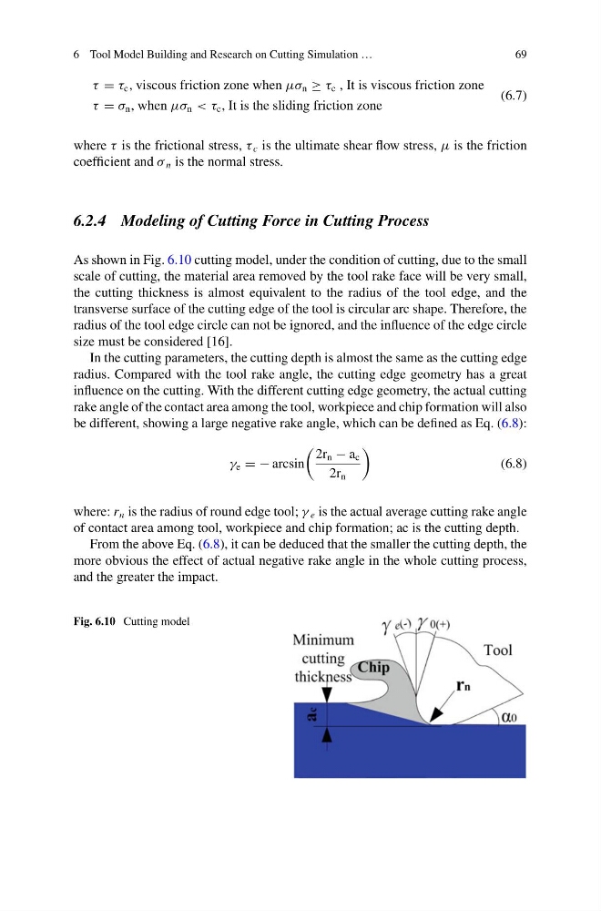
As shown in Fig. 6.10 cutting model, under the condition of cutting, due to the small
scale of cutting, the material area removed by the tool rake face will be very small,
the cutting thickness is almost equivalent to the radius of the tool edge, and the
transverse surface of the cutting edge of the tool is circular arc shape. Therefore, the
radius of the tool edge circle can not be ignored, and the influence of the edge circle
size must be considered [16].
In the cutting parameters, the cutting depth is almost the same as the cutting edge
radius. Compared with the tool rake angle, the cutting edge geometry has a great
influence on the cutting. With the different cutting edge geometry, the actual cutting
rake angle of the contact area among the tool, workpiece and chip formation will also
be different, showing a large negative rake angle, which can be defined as Eq. (6.8):
γ e = − arcsin
2r n − a c
2r n
(6.8)
where: r n is the radius of round edge tool; γ e is the actual average cutting rake angle
of contact area among tool, workpiece and chip formation; ac is the cutting depth.
From the above Eq. (6.8), it can be deduced that the smaller the cutting depth, the
more obvious the effect of actual negative rake angle in the whole cutting process,
and the greater the impact.
Fig. 6.10 Cutting model
69
τ = τ c , viscous friction zone when μσ n ≥ τ c , It is viscous friction zone
τ = σ n , when μσ n < τ c , It is the sliding friction zone
(6.7)
where τ is the frictional stress, τ c is the ultimate shear flow stress, μ is the friction
coefficient and σ n is the normal stress.
6.2.4 Modeling of Cutting Force in Cutting Process
As shown in Fig. 6.10 cutting model, under the condition of cutting, due to the small
scale of cutting, the material area removed by the tool rake face will be very small,
the cutting thickness is almost equivalent to the radius of the tool edge, and the
transverse surface of the cutting edge of the tool is circular arc shape. Therefore, the
radius of the tool edge circle can not be ignored, and the influence of the edge circle
size must be considered [16].
In the cutting parameters, the cutting depth is almost the same as the cutting edge
radius. Compared with the tool rake angle, the cutting edge geometry has a great
influence on the cutting. With the different cutting edge geometry, the actual cutting
rake angle of the contact area among the tool, workpiece and chip formation will also
be different, showing a large negative rake angle, which can be defined as Eq. (6.8):
γ e = − arcsin
2r n − a c
2r n
(6.8)
where: r n is the radius of round edge tool; γ e is the actual average cutting rake angle
of contact area among tool, workpiece and chip formation; ac is the cutting depth.
From the above Eq. (6.8), it can be deduced that the smaller the cutting depth, the
more obvious the effect of actual negative rake angle in the whole cutting process,
and the greater the impact.
Fig. 6.10 Cutting model