

68
Q. Liu et al.
Table 6.3 Johnson–Cook
damage model parameters
d 1
−0.09
d 2
0.25
d 3
−0.5
d 4
−0.014
d 5
3.87
Johnson–Cook Damage Model. In this paper, Johnson–Cook failure model is used
to define failure strain and separate chip from workpiece, as shown in Eq. (6.6).
ε f
pl
=
d 1 + d 2 exp
d 3
P
Q
1 + d 4 ln
˙ ¯
ε
pl
˙
ε 0
1 + d 5
∧
θ
(6.6)
where, P is the pressure; Q is the Mises stress; d 1 −d5 is the failure normal (room
temperature), the parameters are shown in Table 6.3;
•
ε 0 is the reference strain rate;
•pl
ε 0 is the plastic strain rate; and
∧
θ is determined by current temperature, melting point
and room temperature conditions.
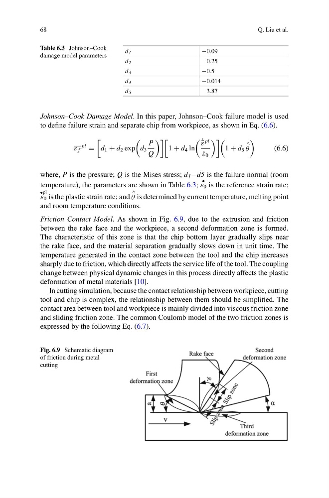
Friction Contact Model. As shown in Fig. 6.9, due to the extrusion and friction
between the rake face and the workpiece, a second deformation zone is formed.
The characteristic of this zone is that the chip bottom layer gradually slips near
the rake face, and the material separation gradually slows down in unit time. The
temperature generated in the contact zone between the tool and the chip increases
sharply due to friction, which directly affects the service life of the tool. The coupling
change between physical dynamic changes in this process directly affects the plastic
deformation of metal materials [10].
In cutting simulation, because the contact relationship between workpiece, cutting
tool and chip is complex, the relationship between them should be simplified. The
contact area between tool and workpiece is mainly divided into viscous friction zone
and sliding friction zone. The common Coulomb model of the two friction zones is
expressed by the following Eq. (6.7).
Fig. 6.9 Schematic diagram
of friction during metal
cutting
Q. Liu et al.
Table 6.3 Johnson–Cook
damage model parameters
d 1
−0.09
d 2
0.25
d 3
−0.5
d 4
−0.014
d 5
3.87
Johnson–Cook Damage Model. In this paper, Johnson–Cook failure model is used
to define failure strain and separate chip from workpiece, as shown in Eq. (6.6).
ε f
pl
=
d 1 + d 2 exp
d 3
P
Q
1 + d 4 ln
˙ ¯
ε
pl
˙
ε 0
1 + d 5
∧
θ
(6.6)
where, P is the pressure; Q is the Mises stress; d 1 −d5 is the failure normal (room
temperature), the parameters are shown in Table 6.3;
•
ε 0 is the reference strain rate;
•pl
ε 0 is the plastic strain rate; and
∧
θ is determined by current temperature, melting point
and room temperature conditions.
Friction Contact Model. As shown in Fig. 6.9, due to the extrusion and friction
between the rake face and the workpiece, a second deformation zone is formed.
The characteristic of this zone is that the chip bottom layer gradually slips near
the rake face, and the material separation gradually slows down in unit time. The
temperature generated in the contact zone between the tool and the chip increases
sharply due to friction, which directly affects the service life of the tool. The coupling
change between physical dynamic changes in this process directly affects the plastic
deformation of metal materials [10].
In cutting simulation, because the contact relationship between workpiece, cutting
tool and chip is complex, the relationship between them should be simplified. The
contact area between tool and workpiece is mainly divided into viscous friction zone
and sliding friction zone. The common Coulomb model of the two friction zones is
expressed by the following Eq. (6.7).
Fig. 6.9 Schematic diagram
of friction during metal
cutting