

64
Q. Liu et al.
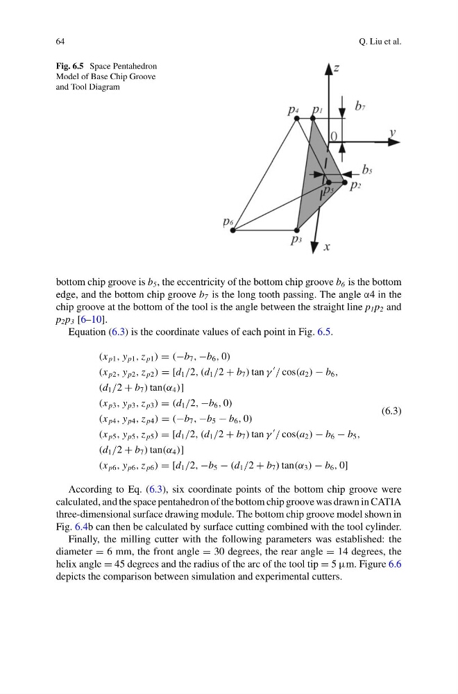
Fig. 6.5 Space Pentahedron
Model of Base Chip Groove
and Tool Diagram
bottom chip groove is b 5 , the eccentricity of the bottom chip groove b 6 is the bottom
edge, and the bottom chip groove b 7 is the long tooth passing. The angle α4 in the
chip groove at the bottom of the tool is the angle between the straight line p 1 p 2 and
p 2 p 3 [6–10].
Equation (6.3) is the coordinate values of each point in Fig. 6.5.
(x p1 , y p1 , z p1 ) = (−b 7 , −b 6 , 0)
(x p2 , y p2 , z p2 ) = [d 1 /2, (d 1 /2 + b 7 ) tan γ
/ cos(a 2 ) − b 6 ,
(d 1 /2 + b 7 ) tan(α 4 )]
(x p3 , y p3 , z p3 ) = (d 1 /2, −b 6 , 0)
(x p4 , y p4 , z p4 ) = (−b 7 , −b 5 − b 6 , 0)
(x p5 , y p5 , z p5 ) = [d 1 /2, (d 1 /2 + b 7 ) tan γ
/ cos(a 2 ) − b 6 − b 5 ,
(d 1 /2 + b 7 ) tan(α 4 )]
(x p6 , y p6 , z p6 ) = [d 1 /2, −b 5 − (d 1 /2 + b 7 ) tan(α 3 ) − b 6 , 0]
(6.3)
According to Eq. (6.3), six coordinate points of the bottom chip groove were
calculated, and the space pentahedron of the bottom chip groove was drawn in CATIA
three-dimensional surface drawing module. The bottom chip groove model shown in
Fig. 6.4b can then be calculated by surface cutting combined with the tool cylinder.
Finally, the milling cutter with the following parameters was established: the
diameter = 6 mm, the front angle = 30 degrees, the rear angle = 14 degrees, the
helix angle = 45 degrees and the radius of the arc of the tool tip = 5 μm. Figure 6.6
depicts the comparison between simulation and experimental cutters.
Q. Liu et al.
Fig. 6.5 Space Pentahedron
Model of Base Chip Groove
and Tool Diagram
bottom chip groove is b 5 , the eccentricity of the bottom chip groove b 6 is the bottom
edge, and the bottom chip groove b 7 is the long tooth passing. The angle α4 in the
chip groove at the bottom of the tool is the angle between the straight line p 1 p 2 and
p 2 p 3 [6–10].
Equation (6.3) is the coordinate values of each point in Fig. 6.5.
(x p1 , y p1 , z p1 ) = (−b 7 , −b 6 , 0)
(x p2 , y p2 , z p2 ) = [d 1 /2, (d 1 /2 + b 7 ) tan γ
/ cos(a 2 ) − b 6 ,
(d 1 /2 + b 7 ) tan(α 4 )]
(x p3 , y p3 , z p3 ) = (d 1 /2, −b 6 , 0)
(x p4 , y p4 , z p4 ) = (−b 7 , −b 5 − b 6 , 0)
(x p5 , y p5 , z p5 ) = [d 1 /2, (d 1 /2 + b 7 ) tan γ
/ cos(a 2 ) − b 6 − b 5 ,
(d 1 /2 + b 7 ) tan(α 4 )]
(x p6 , y p6 , z p6 ) = [d 1 /2, −b 5 − (d 1 /2 + b 7 ) tan(α 3 ) − b 6 , 0]
(6.3)
According to Eq. (6.3), six coordinate points of the bottom chip groove were
calculated, and the space pentahedron of the bottom chip groove was drawn in CATIA
three-dimensional surface drawing module. The bottom chip groove model shown in
Fig. 6.4b can then be calculated by surface cutting combined with the tool cylinder.
Finally, the milling cutter with the following parameters was established: the
diameter = 6 mm, the front angle = 30 degrees, the rear angle = 14 degrees, the
helix angle = 45 degrees and the radius of the arc of the tool tip = 5 μm. Figure 6.6
depicts the comparison between simulation and experimental cutters.