

6 Tool Model Building and Research on Cutting Simulation …
63
I 1
⎧
⎪ ⎪ ⎪ ⎪ ⎪ ⎨
⎪ ⎪ ⎪ ⎪ ⎪ ⎩
x =
d
2
cos θ
2
y =
d
2
sin θ
z =
d
2
θ
tan β
(6.2)
In Fig. 6.3 and Eq. (6.2), d/2 is tool radius, θ is contact angle, β is tool helix angle,
n is spindle speed, F is feed speed, and f Z is the feed per tooth.
Bottom edge of the cutting tool is composed of intersection lines among the
bottom chip flute, the front and back faces of the bottom. The space pentahedron
composed of the front face and the bottom chip groove of the cutting edge of the tool
bottom is called the bottom chip groove of the milling cutter. The geometric size of
the chip flute structure directly relates to the spatial geometry of the cutting edge of
the tool. It not only affects the chip removal performance of cutting tools, but also
affects the stiffness of the tool bottom edge. The chip flute at the bottom of the milling
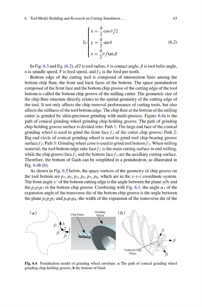
cutter is grinded by ultra-precision grinding with multi-process. Figure 6.4a is the
path of conical grinding wheel grinding chip-holding groove. The path of grinding
chip-holding groove surface is divided into: Path 1: The large end face of the conical
grinding wheel is used to grind the front face f 1 of the cutter chip groove; Path 2:
Big end circle of conical grinding wheel is used to grind tool chip-bearing groove
surface f 2 ; Path 3: Grinding wheel cone is used to grind tool bottom f 3 . When milling
material, the tool bottom edge rake face f 1 is the main cutting surface in end milling,
while the chip groove face f 2 and the bottom face f 3 are the auxiliary cutting surface.
Therefore, the bottom of Gash can be simplified to a pentahedron, as illustrated in
Fig. 6.4b [6].
As shown in Fig. 6.5 below, the space vertices of the geometry of chip groove on
the tool bottom are p 1 , p 2 , p 3 , p 4 , p 5 , p 6 , which are in the x–y-z coordinate system.
The front angle γ
of the bottom cutting edge is the angle between the plane xOy and
the p 1 p 2 p 3 in the bottom chip groove. Combining with Fig. 6.1, the angle α 3 of the
expansion angle of the transverse die of the bottom chip groove is the angle between
the plane p 1 p 2 p 3 and p 4 p 5 p 6 , the width of the expansion of the transverse die of the
Fig. 6.4 Pentahedron model of grinding wheel envelope: a The path of conical grinding wheel
grinding chip-holding groove; b the bottom of Gash
63
I 1
⎧
⎪ ⎪ ⎪ ⎪ ⎪ ⎨
⎪ ⎪ ⎪ ⎪ ⎪ ⎩
x =
d
2
cos θ
2
y =
d
2
sin θ
z =
d
2
θ
tan β
(6.2)
In Fig. 6.3 and Eq. (6.2), d/2 is tool radius, θ is contact angle, β is tool helix angle,
n is spindle speed, F is feed speed, and f Z is the feed per tooth.
Bottom edge of the cutting tool is composed of intersection lines among the
bottom chip flute, the front and back faces of the bottom. The space pentahedron
composed of the front face and the bottom chip groove of the cutting edge of the tool
bottom is called the bottom chip groove of the milling cutter. The geometric size of
the chip flute structure directly relates to the spatial geometry of the cutting edge of
the tool. It not only affects the chip removal performance of cutting tools, but also
affects the stiffness of the tool bottom edge. The chip flute at the bottom of the milling
cutter is grinded by ultra-precision grinding with multi-process. Figure 6.4a is the
path of conical grinding wheel grinding chip-holding groove. The path of grinding
chip-holding groove surface is divided into: Path 1: The large end face of the conical
grinding wheel is used to grind the front face f 1 of the cutter chip groove; Path 2:
Big end circle of conical grinding wheel is used to grind tool chip-bearing groove
surface f 2 ; Path 3: Grinding wheel cone is used to grind tool bottom f 3 . When milling
material, the tool bottom edge rake face f 1 is the main cutting surface in end milling,
while the chip groove face f 2 and the bottom face f 3 are the auxiliary cutting surface.
Therefore, the bottom of Gash can be simplified to a pentahedron, as illustrated in
Fig. 6.4b [6].
As shown in Fig. 6.5 below, the space vertices of the geometry of chip groove on
the tool bottom are p 1 , p 2 , p 3 , p 4 , p 5 , p 6 , which are in the x–y-z coordinate system.
The front angle γ
of the bottom cutting edge is the angle between the plane xOy and
the p 1 p 2 p 3 in the bottom chip groove. Combining with Fig. 6.1, the angle α 3 of the
expansion angle of the transverse die of the bottom chip groove is the angle between
the plane p 1 p 2 p 3 and p 4 p 5 p 6 , the width of the expansion of the transverse die of the
Fig. 6.4 Pentahedron model of grinding wheel envelope: a The path of conical grinding wheel
grinding chip-holding groove; b the bottom of Gash