

26
H. Li et al.
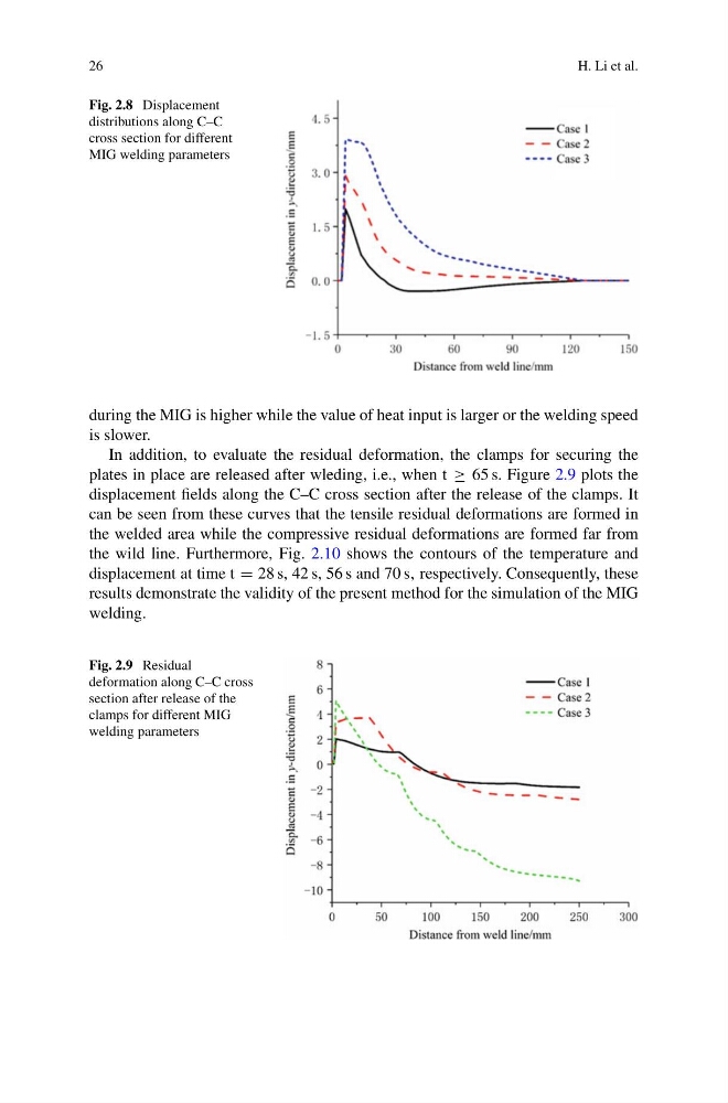
Fig. 2.8 Displacement
distributions along C–C
cross section for different
MIG welding parameters
during the MIG is higher while the value of heat input is larger or the welding speed
is slower.
In addition, to evaluate the residual deformation, the clamps for securing the
plates in place are released after wleding, i.e., when t ≥ 65 s. Figure 2.9 plots the
displacement fields along the C–C cross section after the release of the clamps. It
can be seen from these curves that the tensile residual deformations are formed in
the welded area while the compressive residual deformations are formed far from
the wild line. Furthermore, Fig. 2.10 shows the contours of the temperature and
displacement at time t = 28 s, 42 s, 56 s and 70 s, respectively. Consequently, these
results demonstrate the validity of the present method for the simulation of the MIG
welding.
Fig. 2.9 Residual
deformation along C–C cross
section after release of the
clamps for different MIG
welding parameters
H. Li et al.
Fig. 2.8 Displacement
distributions along C–C
cross section for different
MIG welding parameters
during the MIG is higher while the value of heat input is larger or the welding speed
is slower.
In addition, to evaluate the residual deformation, the clamps for securing the
plates in place are released after wleding, i.e., when t ≥ 65 s. Figure 2.9 plots the
displacement fields along the C–C cross section after the release of the clamps. It
can be seen from these curves that the tensile residual deformations are formed in
the welded area while the compressive residual deformations are formed far from
the wild line. Furthermore, Fig. 2.10 shows the contours of the temperature and
displacement at time t = 28 s, 42 s, 56 s and 70 s, respectively. Consequently, these
results demonstrate the validity of the present method for the simulation of the MIG
welding.
Fig. 2.9 Residual
deformation along C–C cross
section after release of the
clamps for different MIG
welding parameters