

246
F. Liang et al.
19.2.4 Establishment of Co-Simulation System Model
Parallel robot is a MIMO, highly nonlinear and strong coupling system, and its
control problem is always a difficult problem. Parallel robot relies on reasonable and
practical control strategy to give full play to its performance potential. The control
strategy will directly determine the final performance index of the system. In practice,
the traditional PID control algorithm is still widely used. The most commonly used
control strategy of 6-DOF Parallel robot is PID control. In this control method, PID
controllers control the posture of the moving platform by controlling six struts to
complete their respective actions.
In order to carry out the co-simulation of ADAMS and MATLAB and realize the
parameter transfer between mechanical system and control system, it is necessary to
use ADAMS/control interface module. After the input and output variables required
by the co-simulation system are established in ADAMS, the 6-DOF parallel robot
system in ADAMS is imported into MATLAB as a subsystem of MATLAB/Simulink,
so as to realize the co-simulation of mechanical and control system.
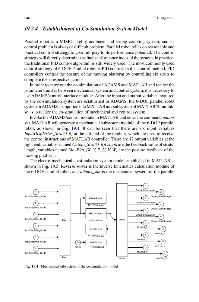
Invoke the ADAMS/control module in MATLAB and enter the command adams
sys, MATLAB will generate a mechanical subsystem module of the 6-DOF parallel
robot, as shown in Fig. 19.4. It can be seen that there are six input variables
InputDispDrive_Strut(1-6) at the left end of the module, which are used to receive
the control instructions of MATLAB controller. There are 12 output variables at the
right end, variables named Output_Strut(1-6)Length are the feedback value of struts’
length, variables named MovPlat_(X, Y, Z, U, V, W) are the posture feedback of the
moving platform.
The electro-mechanical co-simulation system model established in MATLAB is
shown in Fig. 19.5. Reverse solver is the inverse kinematics calculation module of
the 6-DOF parallel robot, and adams_sub is the mechanical system of the parallel
12
MovPlat_W
11
MovPlat_V
10
MovPlat_U
9
MovPlat_Z
8
MovPlat_Y
7
MovPlat_X
6
Output_Strut6Length
5
Output_Strut5Length
4
Output_Strut4Length
3
Output_Strut3Length
2
Output_Strut2Length
1
Output_Strut1Length
ADAMS_yout
Y To Workspace
ADAMS_uout
U To Workspace
ADAMS_tout
T To Workspace
Mux
Mux
Demux
Demux
Clock
MSC Software
ADAMS Plant
6
InputDispDrive_Strut6
5
InputDispDrive_Strut5
4
InputDispDrive_Strut4
3
InputDispDrive_Strut3
2
InputDispDrive_Strut2
1
InputDispDrive_Strut1
Fig. 19.4 Mechanical subsystem of the co-simulation model
F. Liang et al.
19.2.4 Establishment of Co-Simulation System Model
Parallel robot is a MIMO, highly nonlinear and strong coupling system, and its
control problem is always a difficult problem. Parallel robot relies on reasonable and
practical control strategy to give full play to its performance potential. The control
strategy will directly determine the final performance index of the system. In practice,
the traditional PID control algorithm is still widely used. The most commonly used
control strategy of 6-DOF Parallel robot is PID control. In this control method, PID
controllers control the posture of the moving platform by controlling six struts to
complete their respective actions.
In order to carry out the co-simulation of ADAMS and MATLAB and realize the
parameter transfer between mechanical system and control system, it is necessary to
use ADAMS/control interface module. After the input and output variables required
by the co-simulation system are established in ADAMS, the 6-DOF parallel robot
system in ADAMS is imported into MATLAB as a subsystem of MATLAB/Simulink,
so as to realize the co-simulation of mechanical and control system.
Invoke the ADAMS/control module in MATLAB and enter the command adams
sys, MATLAB will generate a mechanical subsystem module of the 6-DOF parallel
robot, as shown in Fig. 19.4. It can be seen that there are six input variables
InputDispDrive_Strut(1-6) at the left end of the module, which are used to receive
the control instructions of MATLAB controller. There are 12 output variables at the
right end, variables named Output_Strut(1-6)Length are the feedback value of struts’
length, variables named MovPlat_(X, Y, Z, U, V, W) are the posture feedback of the
moving platform.
The electro-mechanical co-simulation system model established in MATLAB is
shown in Fig. 19.5. Reverse solver is the inverse kinematics calculation module of
the 6-DOF parallel robot, and adams_sub is the mechanical system of the parallel
12
MovPlat_W
11
MovPlat_V
10
MovPlat_U
9
MovPlat_Z
8
MovPlat_Y
7
MovPlat_X
6
Output_Strut6Length
5
Output_Strut5Length
4
Output_Strut4Length
3
Output_Strut3Length
2
Output_Strut2Length
1
Output_Strut1Length
ADAMS_yout
Y To Workspace
ADAMS_uout
U To Workspace
ADAMS_tout
T To Workspace
Mux
Mux
Demux
Demux
Clock
MSC Software
ADAMS Plant
6
InputDispDrive_Strut6
5
InputDispDrive_Strut5
4
InputDispDrive_Strut4
3
InputDispDrive_Strut3
2
InputDispDrive_Strut2
1
InputDispDrive_Strut1
Fig. 19.4 Mechanical subsystem of the co-simulation model