

244
F. Liang et al.
⎡
⎣
cV cW
−sV sW
sV
sU sV cW + cU sW −sU sV sW + cU cW −cV sU
−cU sV cW + sU sW cU sV sW + sU cW cU cV
⎤
⎦
(19.1)
where cU = cos (U), cV = cos (V), cW = cos (W), sU = sin (U), sV = sin (V), sW
= sin (W). When the generalized coordinates of the posture of the moving platform
are q = [X, Y, Z, U, V, W ]
T , the length of each strut is can be defined in Eq. (19.2):
l i = |l i | =
l
T
i · l i
(19.2)
where the vector l i is the strut vector A i B i shown in Fig. 19.1, l i is the length of
the struts, i = 1, 2, …, 6. So far, the inverse kinematics mathematical model of the
6-DOF parallel robot is established.
19.2.2 Kinematics Simulation
In order to study the kinematics simulation of the 6-DOF parallel robot in ADAMS,
the virtual prototype model must be established in ADAMS. ADAMS provides the
function of parametric modeling, that is, the eigenvalues of the established model
are expressed by the design parameters in ADAMS. In this way, the model will
automatically change with the modification of design parameters, greatly simplifying the manual modification process, especially conducive to the optimal design
of mechanical structure.
In ADAMS/view, the coordinates of the upper hinge points B i , the lower hinge
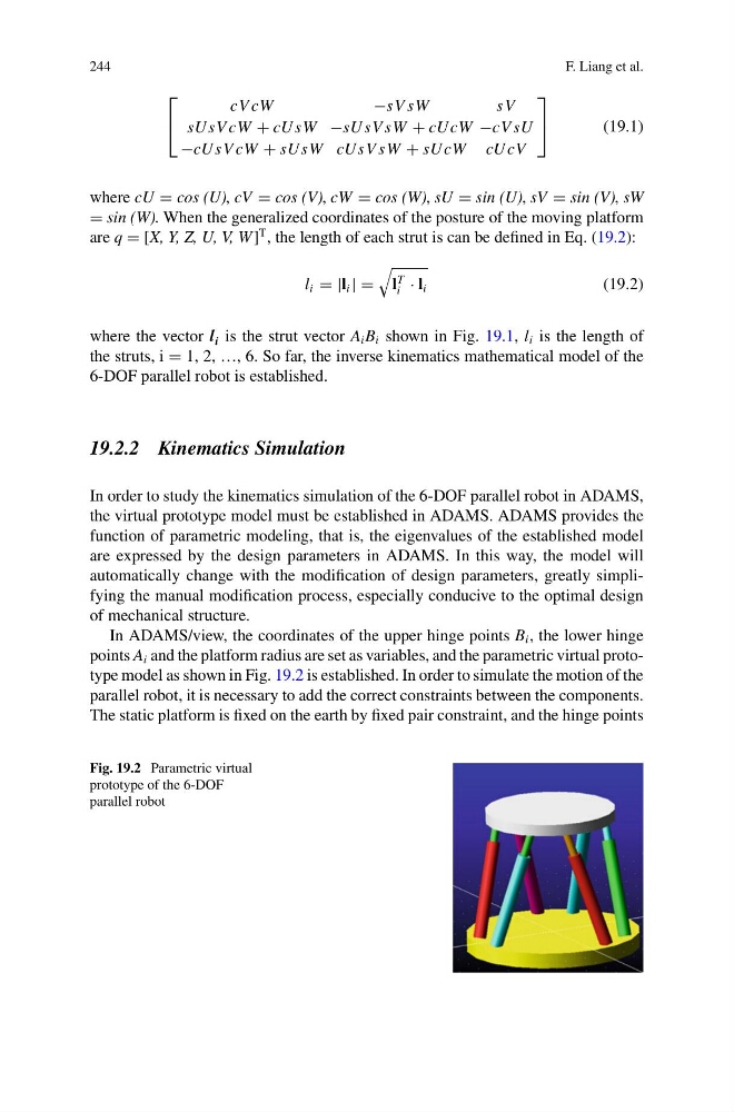
points A i and the platform radius are set as variables, and the parametric virtual prototype model as shown in Fig. 19.2 is established. In order to simulate the motion of the
parallel robot, it is necessary to add the correct constraints between the components.
The static platform is fixed on the earth by fixed pair constraint, and the hinge points
Fig. 19.2 Parametric virtual
prototype of the 6-DOF
parallel robot
F. Liang et al.
⎡
⎣
cV cW
−sV sW
sV
sU sV cW + cU sW −sU sV sW + cU cW −cV sU
−cU sV cW + sU sW cU sV sW + sU cW cU cV
⎤
⎦
(19.1)
where cU = cos (U), cV = cos (V), cW = cos (W), sU = sin (U), sV = sin (V), sW
= sin (W). When the generalized coordinates of the posture of the moving platform
are q = [X, Y, Z, U, V, W ]
T , the length of each strut is can be defined in Eq. (19.2):
l i = |l i | =
l
T
i · l i
(19.2)
where the vector l i is the strut vector A i B i shown in Fig. 19.1, l i is the length of
the struts, i = 1, 2, …, 6. So far, the inverse kinematics mathematical model of the
6-DOF parallel robot is established.
19.2.2 Kinematics Simulation
In order to study the kinematics simulation of the 6-DOF parallel robot in ADAMS,
the virtual prototype model must be established in ADAMS. ADAMS provides the
function of parametric modeling, that is, the eigenvalues of the established model
are expressed by the design parameters in ADAMS. In this way, the model will
automatically change with the modification of design parameters, greatly simplifying the manual modification process, especially conducive to the optimal design
of mechanical structure.
In ADAMS/view, the coordinates of the upper hinge points B i , the lower hinge
points A i and the platform radius are set as variables, and the parametric virtual prototype model as shown in Fig. 19.2 is established. In order to simulate the motion of the
parallel robot, it is necessary to add the correct constraints between the components.
The static platform is fixed on the earth by fixed pair constraint, and the hinge points
Fig. 19.2 Parametric virtual
prototype of the 6-DOF
parallel robot