

19 Electro-Mechanical Co-Simulation of a 6-DOF …
243
19.2 Kinematics Analysis of the Parallel Robot
19.2.1 Theoretical Basis
Kinematics analysis is the basis of dynamic analysis, structural optimization design
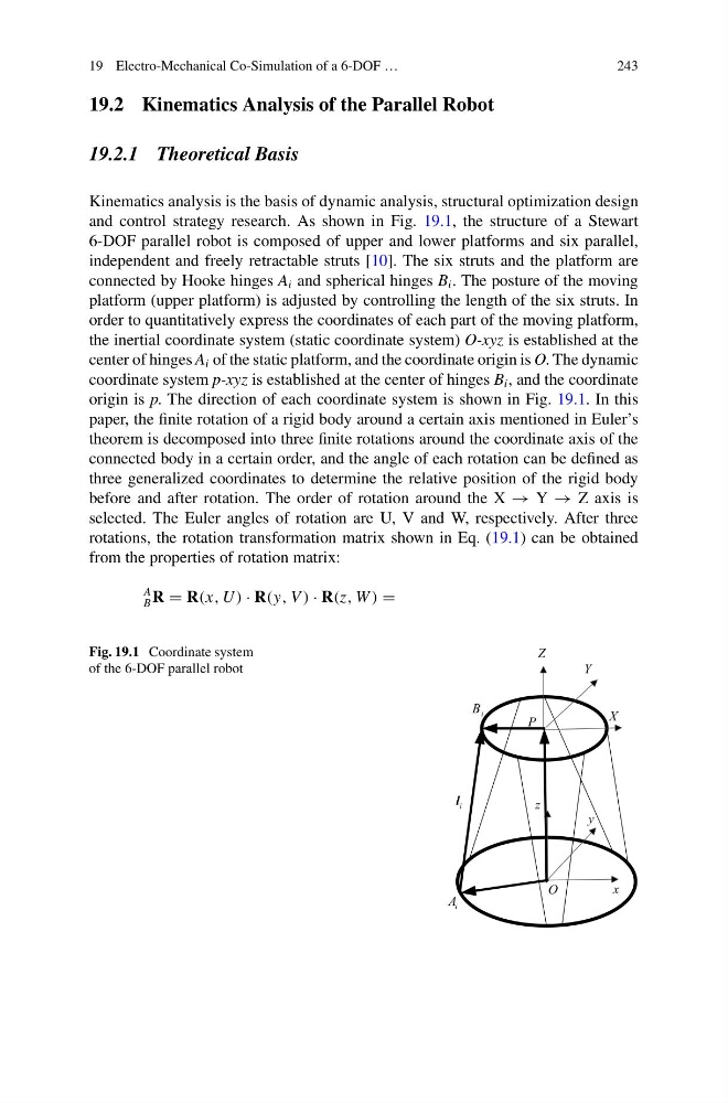
and control strategy research. As shown in Fig. 19.1, the structure of a Stewart
6-DOF parallel robot is composed of upper and lower platforms and six parallel,
independent and freely retractable struts [10]. The six struts and the platform are
connected by Hooke hinges A i and spherical hinges B i . The posture of the moving
platform (upper platform) is adjusted by controlling the length of the six struts. In
order to quantitatively express the coordinates of each part of the moving platform,
the inertial coordinate system (static coordinate system) O-xyz is established at the
center of hinges A i of the static platform, and the coordinate origin is O. The dynamic
coordinate system p-xyz is established at the center of hinges B i , and the coordinate
origin is p. The direction of each coordinate system is shown in Fig. 19.1. In this
paper, the finite rotation of a rigid body around a certain axis mentioned in Euler’s
theorem is decomposed into three finite rotations around the coordinate axis of the
connected body in a certain order, and the angle of each rotation can be defined as
three generalized coordinates to determine the relative position of the rigid body
before and after rotation. The order of rotation around the X → Y → Z axis is
selected. The Euler angles of rotation are U, V and W, respectively. After three
rotations, the rotation transformation matrix shown in Eq. (19.1) can be obtained
from the properties of rotation matrix:
A
B R = R(x, U ) · R(y, V ) · R(z, W ) =
Fig. 19.1 Coordinate system
of the 6-DOF parallel robot
x
y
z
Y
X
Z
P
O
i
B
i
A
i
l
243
19.2 Kinematics Analysis of the Parallel Robot
19.2.1 Theoretical Basis
Kinematics analysis is the basis of dynamic analysis, structural optimization design
and control strategy research. As shown in Fig. 19.1, the structure of a Stewart
6-DOF parallel robot is composed of upper and lower platforms and six parallel,
independent and freely retractable struts [10]. The six struts and the platform are
connected by Hooke hinges A i and spherical hinges B i . The posture of the moving
platform (upper platform) is adjusted by controlling the length of the six struts. In
order to quantitatively express the coordinates of each part of the moving platform,
the inertial coordinate system (static coordinate system) O-xyz is established at the
center of hinges A i of the static platform, and the coordinate origin is O. The dynamic
coordinate system p-xyz is established at the center of hinges B i , and the coordinate
origin is p. The direction of each coordinate system is shown in Fig. 19.1. In this
paper, the finite rotation of a rigid body around a certain axis mentioned in Euler’s
theorem is decomposed into three finite rotations around the coordinate axis of the
connected body in a certain order, and the angle of each rotation can be defined as
three generalized coordinates to determine the relative position of the rigid body
before and after rotation. The order of rotation around the X → Y → Z axis is
selected. The Euler angles of rotation are U, V and W, respectively. After three
rotations, the rotation transformation matrix shown in Eq. (19.1) can be obtained
from the properties of rotation matrix:
A
B R = R(x, U ) · R(y, V ) · R(z, W ) =
Fig. 19.1 Coordinate system
of the 6-DOF parallel robot
x
y
z
Y
X
Z
P
O
i
B
i
A
i
l