

18 The Effect of Surface Ultrasonic Rolling Processing …
225
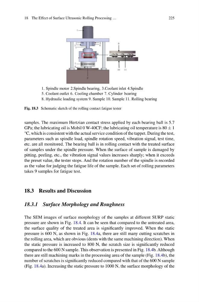
1. Spindle motor 2.Spindle bearing, 3.Coolant inlet 4.Spindle
5. Coolant outlet 6. Cooling chamber 7. Cylinder bearing
8. Hydraulic loading system 9. Sample 10. Sample 11. Rolling bearing
Fig. 18.3 Schematic sketch of the rolling contact fatigue tester
samples. The maximum Hertzian contact stress applied by each bearing ball is 5.7
GPa; the lubricating oil is Mobil 0 W-40CF; the lubricating oil temperature is 80 ± 1
°C, which is consistent with the actual service condition of the tappet. During the test,
parameters such as spindle load, spindle rotation speed, vibration signal, test time,
etc. are all monitored. The bearing ball is in rolling contact with the treated surface
of samples under the spindle pressure. When the surface of sample is damaged by
pitting, peeling, etc., the vibration signal values increases sharply; when it exceeds
the preset value, the tester stops. And the rotation number of the spindle is recorded
as the value for judging the fatigue life of the sample. Each set of rolling parameters
takes 9 samples for fatigue test.
18.3 Results and Discussion
18.3.1 Surface Morphology and Roughness
The SEM images of surface morphology of the samples at different SURP static
pressure are shown in Fig. 18.4. It can be seen that compared to the untreated area,
the surface quality of the treated area is significantly improved. When the static
pressure is 600 N, as shown in Fig. 18.4a, there are still many cutting scratches in
the rolling area, which are obvious (dents with the same machining direction). When
the static pressure is increased to 800 N, the scratch size is significantly reduced
compared to the 600 N sample. This observation is presented in Fig. 18.4b. Although
there are still machining marks in the processing area of the sample (Fig. 18.4b), the
number of scratches is significantly reduced compared with that of the 600 N sample
(Fig. 18.4a). Increasing the static pressure to 1000 N, the surface morphology of the
225
1. Spindle motor 2.Spindle bearing, 3.Coolant inlet 4.Spindle
5. Coolant outlet 6. Cooling chamber 7. Cylinder bearing
8. Hydraulic loading system 9. Sample 10. Sample 11. Rolling bearing
Fig. 18.3 Schematic sketch of the rolling contact fatigue tester
samples. The maximum Hertzian contact stress applied by each bearing ball is 5.7
GPa; the lubricating oil is Mobil 0 W-40CF; the lubricating oil temperature is 80 ± 1
°C, which is consistent with the actual service condition of the tappet. During the test,
parameters such as spindle load, spindle rotation speed, vibration signal, test time,
etc. are all monitored. The bearing ball is in rolling contact with the treated surface
of samples under the spindle pressure. When the surface of sample is damaged by
pitting, peeling, etc., the vibration signal values increases sharply; when it exceeds
the preset value, the tester stops. And the rotation number of the spindle is recorded
as the value for judging the fatigue life of the sample. Each set of rolling parameters
takes 9 samples for fatigue test.
18.3 Results and Discussion
18.3.1 Surface Morphology and Roughness
The SEM images of surface morphology of the samples at different SURP static
pressure are shown in Fig. 18.4. It can be seen that compared to the untreated area,
the surface quality of the treated area is significantly improved. When the static
pressure is 600 N, as shown in Fig. 18.4a, there are still many cutting scratches in
the rolling area, which are obvious (dents with the same machining direction). When
the static pressure is increased to 800 N, the scratch size is significantly reduced
compared to the 600 N sample. This observation is presented in Fig. 18.4b. Although
there are still machining marks in the processing area of the sample (Fig. 18.4b), the
number of scratches is significantly reduced compared with that of the 600 N sample
(Fig. 18.4a). Increasing the static pressure to 1000 N, the surface morphology of the