

214
L. Zhao et al.
The bending stress determined in GATES is similar to ISO 6336 standard, calculating the bending stress at 30 degree tangent position, except the load distribution is
calculated from the TCA, stiffness variation across the face width and compressive
load is considered.
A critical point for bending stress determined by GATES is extended contact
which occurs as the loaded tooth is restored to its original un-deflected state at the
end of active profile [15]. If tip relief is not applied, the extended contact will increase
the contact ratio thus lowering the actual HPSTC (for spur gear, the bending stress
is calculated with load applied at the highest point of single tooth contact (HPSTC))
and then lower the actual bending stress. If too much tip relief is applied, the loading
point will increases which will increase the bending stress. Therefore bending stress
derived from GATES must be calculated with correct tip relief to make sure the gear
loaded at exactly the same position as ISO (HPSTC). In this study, to ensure the
results from GATES are valid, the correct tip relief are applied to gears.
17.3.3 Finite Element Analysis
In recent years, finite element analysis is widely used to evaluate gear stress, resulting
in an abundance of published research [16, 17]. According to [16], in this study, the
finite element analysis of gear bending stress is set as follows:
(1) Three teeth are used to calculate gear stress.
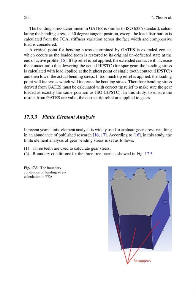
(2) Boundary conditions: fix the three free faces as showed in Fig. 17.3.
Fig. 17.3 The boundary
conditions of bending stress
calculation in FEA
L. Zhao et al.
The bending stress determined in GATES is similar to ISO 6336 standard, calculating the bending stress at 30 degree tangent position, except the load distribution is
calculated from the TCA, stiffness variation across the face width and compressive
load is considered.
A critical point for bending stress determined by GATES is extended contact
which occurs as the loaded tooth is restored to its original un-deflected state at the
end of active profile [15]. If tip relief is not applied, the extended contact will increase
the contact ratio thus lowering the actual HPSTC (for spur gear, the bending stress
is calculated with load applied at the highest point of single tooth contact (HPSTC))
and then lower the actual bending stress. If too much tip relief is applied, the loading
point will increases which will increase the bending stress. Therefore bending stress
derived from GATES must be calculated with correct tip relief to make sure the gear
loaded at exactly the same position as ISO (HPSTC). In this study, to ensure the
results from GATES are valid, the correct tip relief are applied to gears.
17.3.3 Finite Element Analysis
In recent years, finite element analysis is widely used to evaluate gear stress, resulting
in an abundance of published research [16, 17]. According to [16], in this study, the
finite element analysis of gear bending stress is set as follows:
(1) Three teeth are used to calculate gear stress.
(2) Boundary conditions: fix the three free faces as showed in Fig. 17.3.
Fig. 17.3 The boundary
conditions of bending stress
calculation in FEA