

17 The Influence of Pressure Angle of Spur Gears …
215
(3) Mesh types: automatic mesh method.
(4) Element size is defined in Eqs. (17.7) and (17.8):
M bending = 0.2ρ F + 0.15 For ρ F > 0.5mm
(17.7)
M bending = 0.366ρ
0.614
F
For ρ F ≤ 0.5mm
(17.8)
(5) Maximum principal stress is used to represent the gear stress.
(6) Use smaller element sizes to verify the validity of the maximum bending stress
to ensure the consistency of the results.
17.4 Results and Discussions
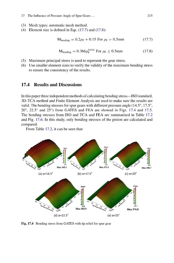
In this paper three independent methods of calculating bending stress—ISO standard,
3D-TCA method and Finite Element Analysis are used to make sure the results are
valid. The bending stresses for spur gears with different pressure angle (14.5°, 17.5°,
20°, 22.5° and 25°) from GATES and FEA are showed in Figs. 17.4 and 17.5.
The bending stresses from ISO and TCA and FEA are summarized in Table 17.2
and Fig. 17.6. In this study, only bending stresses of the pinion are calculated and
compared.
From Table 17.2, it can be seen that:
(a) α=14.5
(b) α=17.5
(c) α=20
(d) α=22.5
(e) α=25
Fig. 17.4 Bending stress from GATES with tip relief for spur gear
215
(3) Mesh types: automatic mesh method.
(4) Element size is defined in Eqs. (17.7) and (17.8):
M bending = 0.2ρ F + 0.15 For ρ F > 0.5mm
(17.7)
M bending = 0.366ρ
0.614
F
For ρ F ≤ 0.5mm
(17.8)
(5) Maximum principal stress is used to represent the gear stress.
(6) Use smaller element sizes to verify the validity of the maximum bending stress
to ensure the consistency of the results.
17.4 Results and Discussions
In this paper three independent methods of calculating bending stress—ISO standard,
3D-TCA method and Finite Element Analysis are used to make sure the results are
valid. The bending stresses for spur gears with different pressure angle (14.5°, 17.5°,
20°, 22.5° and 25°) from GATES and FEA are showed in Figs. 17.4 and 17.5.
The bending stresses from ISO and TCA and FEA are summarized in Table 17.2
and Fig. 17.6. In this study, only bending stresses of the pinion are calculated and
compared.
From Table 17.2, it can be seen that:
(a) α=14.5
(b) α=17.5
(c) α=20
(d) α=22.5
(e) α=25
Fig. 17.4 Bending stress from GATES with tip relief for spur gear