

17 The Influence of Pressure Angle of Spur Gears …
213
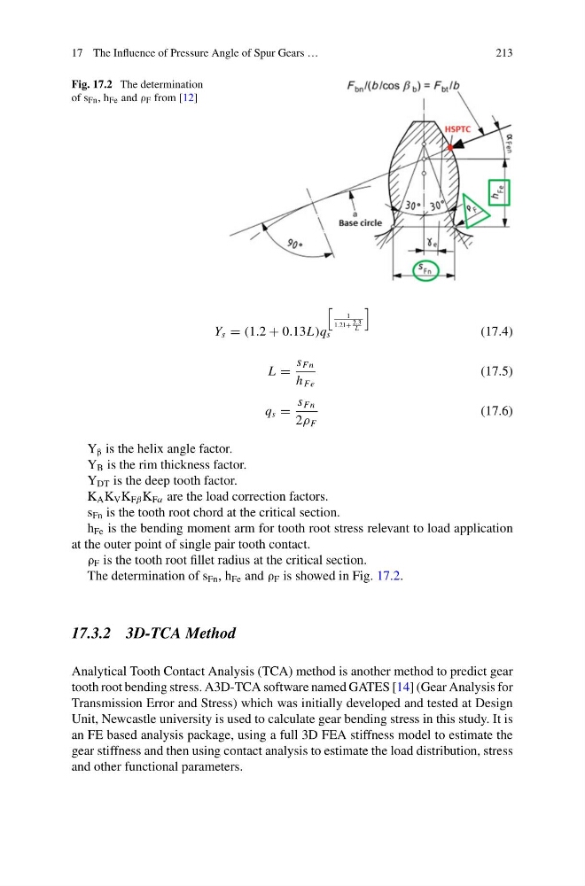
Fig. 17.2 The determination
of s Fn , h Fe and ρ F from [12]
Y s = (1.2 + 0.13L)q
1
1.21+ 2.3
L
s
(17.4)
L =
s Fn
h Fe
(17.5)
q s =
s Fn
2ρ F
(17.6)
Y β is the helix angle factor.
Y B is the rim thickness factor.
Y DT is the deep tooth factor.
K A K V K Fβ K Fα are the load correction factors.
s Fn is the tooth root chord at the critical section.
h Fe is the bending moment arm for tooth root stress relevant to load application
at the outer point of single pair tooth contact.
ρ F is the tooth root fillet radius at the critical section.
The determination of s Fn , h Fe and ρ F is showed in Fig. 17.2.
17.3.2 3D-TCA Method
Analytical Tooth Contact Analysis (TCA) method is another method to predict gear
tooth root bending stress. A3D-TCA software named GATES [14] (Gear Analysis for
Transmission Error and Stress) which was initially developed and tested at Design
Unit, Newcastle university is used to calculate gear bending stress in this study. It is
an FE based analysis package, using a full 3D FEA stiffness model to estimate the
gear stiffness and then using contact analysis to estimate the load distribution, stress
and other functional parameters.
213
Fig. 17.2 The determination
of s Fn , h Fe and ρ F from [12]
Y s = (1.2 + 0.13L)q
1
1.21+ 2.3
L
s
(17.4)
L =
s Fn
h Fe
(17.5)
q s =
s Fn
2ρ F
(17.6)
Y β is the helix angle factor.
Y B is the rim thickness factor.
Y DT is the deep tooth factor.
K A K V K Fβ K Fα are the load correction factors.
s Fn is the tooth root chord at the critical section.
h Fe is the bending moment arm for tooth root stress relevant to load application
at the outer point of single pair tooth contact.
ρ F is the tooth root fillet radius at the critical section.
The determination of s Fn , h Fe and ρ F is showed in Fig. 17.2.
17.3.2 3D-TCA Method
Analytical Tooth Contact Analysis (TCA) method is another method to predict gear
tooth root bending stress. A3D-TCA software named GATES [14] (Gear Analysis for
Transmission Error and Stress) which was initially developed and tested at Design
Unit, Newcastle university is used to calculate gear bending stress in this study. It is
an FE based analysis package, using a full 3D FEA stiffness model to estimate the
gear stiffness and then using contact analysis to estimate the load distribution, stress
and other functional parameters.