

13 Study on Bearing Mechanism of Composite Stiffened Panel …
165
a) Intralaminar
damage initiation
b) Intralaminar damage
local propagation
c) Intralaminar damage
global propagation
d) Intralaminar
failure
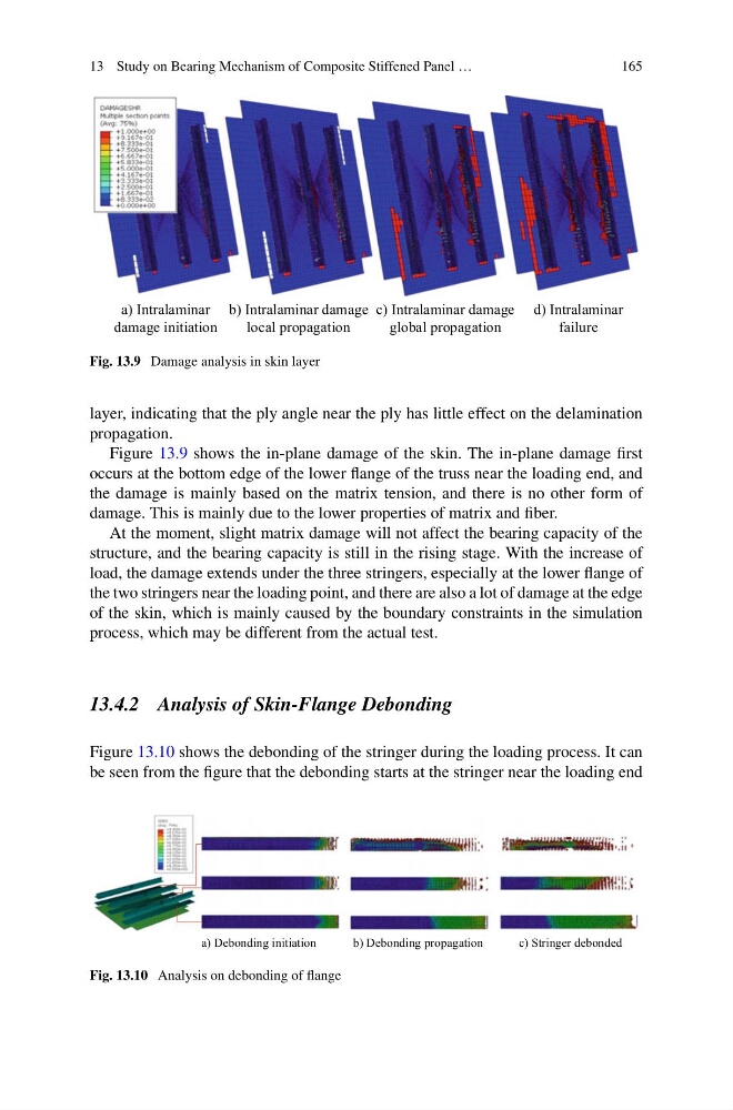
Fig. 13.9 Damage analysis in skin layer
layer, indicating that the ply angle near the ply has little effect on the delamination
propagation.
Figure 13.9 shows the in-plane damage of the skin. The in-plane damage first
occurs at the bottom edge of the lower flange of the truss near the loading end, and
the damage is mainly based on the matrix tension, and there is no other form of
damage. This is mainly due to the lower properties of matrix and fiber.
At the moment, slight matrix damage will not affect the bearing capacity of the
structure, and the bearing capacity is still in the rising stage. With the increase of
load, the damage extends under the three stringers, especially at the lower flange of
the two stringers near the loading point, and there are also a lot of damage at the edge
of the skin, which is mainly caused by the boundary constraints in the simulation
process, which may be different from the actual test.
13.4.2 Analysis of Skin-Flange Debonding
Figure 13.10 shows the debonding of the stringer during the loading process. It can
be seen from the figure that the debonding starts at the stringer near the loading end
a) Debonding initiation
b) Debonding propagation
c) Stringer debonded
Fig. 13.10 Analysis on debonding of flange
165
a) Intralaminar
damage initiation
b) Intralaminar damage
local propagation
c) Intralaminar damage
global propagation
d) Intralaminar
failure
Fig. 13.9 Damage analysis in skin layer
layer, indicating that the ply angle near the ply has little effect on the delamination
propagation.
Figure 13.9 shows the in-plane damage of the skin. The in-plane damage first
occurs at the bottom edge of the lower flange of the truss near the loading end, and
the damage is mainly based on the matrix tension, and there is no other form of
damage. This is mainly due to the lower properties of matrix and fiber.
At the moment, slight matrix damage will not affect the bearing capacity of the
structure, and the bearing capacity is still in the rising stage. With the increase of
load, the damage extends under the three stringers, especially at the lower flange of
the two stringers near the loading point, and there are also a lot of damage at the edge
of the skin, which is mainly caused by the boundary constraints in the simulation
process, which may be different from the actual test.
13.4.2 Analysis of Skin-Flange Debonding
Figure 13.10 shows the debonding of the stringer during the loading process. It can
be seen from the figure that the debonding starts at the stringer near the loading end
a) Debonding initiation
b) Debonding propagation
c) Stringer debonded
Fig. 13.10 Analysis on debonding of flange