

166
X. Bi et al.
a) Stringer damage
initiation
b) Stringer damage
propagation
c) Extensive stringer
damage
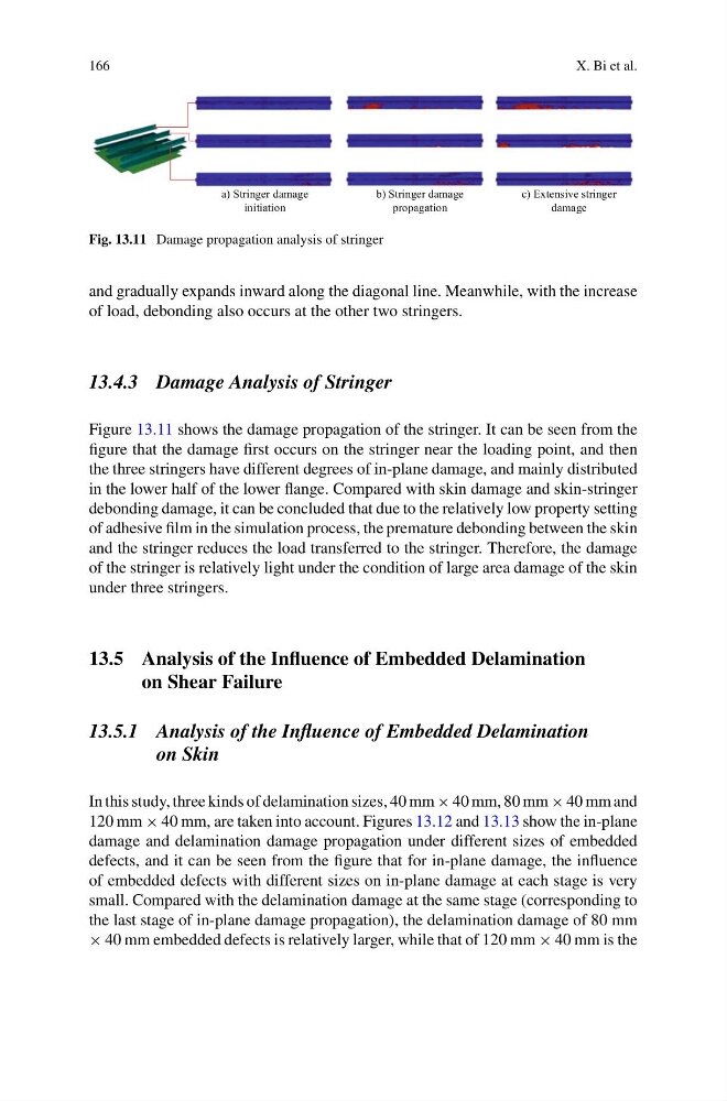
Fig. 13.11 Damage propagation analysis of stringer
and gradually expands inward along the diagonal line. Meanwhile, with the increase
of load, debonding also occurs at the other two stringers.
13.4.3 Damage Analysis of Stringer
Figure 13.11 shows the damage propagation of the stringer. It can be seen from the
figure that the damage first occurs on the stringer near the loading point, and then
the three stringers have different degrees of in-plane damage, and mainly distributed
in the lower half of the lower flange. Compared with skin damage and skin-stringer
debonding damage, it can be concluded that due to the relatively low property setting
of adhesive film in the simulation process, the premature debonding between the skin
and the stringer reduces the load transferred to the stringer. Therefore, the damage
of the stringer is relatively light under the condition of large area damage of the skin
under three stringers.
13.5 Analysis of the Influence of Embedded Delamination
on Shear Failure
13.5.1 Analysis of the Influence of Embedded Delamination
on Skin
In this study, three kinds of delamination sizes, 40 mm × 40 mm, 80 mm × 40 mm and
120 mm × 40 mm, are taken into account. Figures 13.12 and 13.13 show the in-plane
damage and delamination damage propagation under different sizes of embedded
defects, and it can be seen from the figure that for in-plane damage, the influence
of embedded defects with different sizes on in-plane damage at each stage is very
small. Compared with the delamination damage at the same stage (corresponding to
the last stage of in-plane damage propagation), the delamination damage of 80 mm
× 40 mm embedded defects is relatively larger, while that of 120 mm × 40 mm is the
X. Bi et al.
a) Stringer damage
initiation
b) Stringer damage
propagation
c) Extensive stringer
damage
Fig. 13.11 Damage propagation analysis of stringer
and gradually expands inward along the diagonal line. Meanwhile, with the increase
of load, debonding also occurs at the other two stringers.
13.4.3 Damage Analysis of Stringer
Figure 13.11 shows the damage propagation of the stringer. It can be seen from the
figure that the damage first occurs on the stringer near the loading point, and then
the three stringers have different degrees of in-plane damage, and mainly distributed
in the lower half of the lower flange. Compared with skin damage and skin-stringer
debonding damage, it can be concluded that due to the relatively low property setting
of adhesive film in the simulation process, the premature debonding between the skin
and the stringer reduces the load transferred to the stringer. Therefore, the damage
of the stringer is relatively light under the condition of large area damage of the skin
under three stringers.
13.5 Analysis of the Influence of Embedded Delamination
on Shear Failure
13.5.1 Analysis of the Influence of Embedded Delamination
on Skin
In this study, three kinds of delamination sizes, 40 mm × 40 mm, 80 mm × 40 mm and
120 mm × 40 mm, are taken into account. Figures 13.12 and 13.13 show the in-plane
damage and delamination damage propagation under different sizes of embedded
defects, and it can be seen from the figure that for in-plane damage, the influence
of embedded defects with different sizes on in-plane damage at each stage is very
small. Compared with the delamination damage at the same stage (corresponding to
the last stage of in-plane damage propagation), the delamination damage of 80 mm
× 40 mm embedded defects is relatively larger, while that of 120 mm × 40 mm is the