

6
Y. Wang and Y. Zeng
GH4169 (Shanghai INESA Scientific Instrument Co., Ltd., thickness: 1 mm) is fixed
into the electrochemical cell mounted on the piezo transducer (P561.3CD, PI Co.).
The workpiece was cleaned by acetone, ethanol, and deionized water in sequence.
The piezo transducer allows the workpiece to move in three-dimensional directions
with a resolution of 0.8 nm and a range of 100 μm.
To set the initial inter-electrode gap, the tip approached the workpiece by feeding
the Z-axis linear stage (M511.HD, PI Co.), while applying a small tip-workpiece
voltage. The electric short circuit response has been used for determining the tipworkpiece distance [21]. The tip advances to the workpiece at a rate of 0.1 μm/step
under a small potential 2 V. The position where an electric short circuit occurs
was defined as zero point. Afterward, the tip retreated at the controlled initial
tip-workpiece gap. An electrolyte solution of 0.1 M H2SO 4 served as the electrolyte. During EMM, a pulse voltage with the period 500 ns, pulse duration 45 ns,
and varying voltage was provided by a high-frequency pulse generator (8110A,
KEYSIGHT Co.), in order to localize the machining area in the proximity of the
spherical tip, and thus reduce the effect of stray current corrosion. An atomic force
microscope (AFM, Dimensional Edge, Bruker Co.) was employed to characterize
the three-dimensional profile of the machined microchannels. The precision of EMM
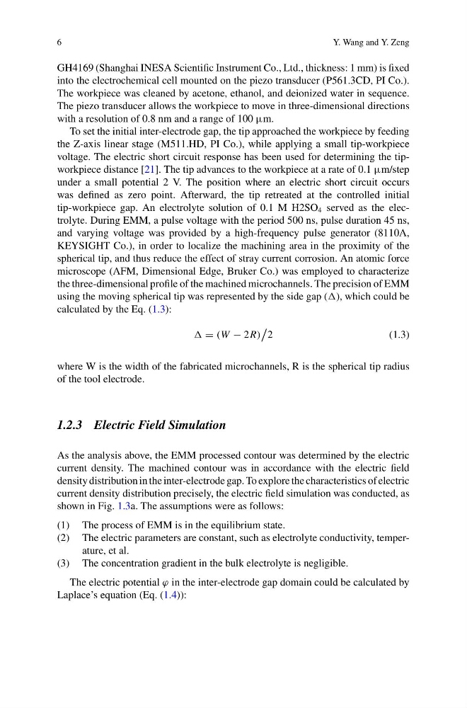
using the moving spherical tip was represented by the side gap (), which could be
calculated by the Eq. (1.3):
= (W − 2R)
2
(1.3)
where W is the width of the fabricated microchannels, R is the spherical tip radius
of the tool electrode.
1.2.3 Electric Field Simulation
As the analysis above, the EMM processed contour was determined by the electric
current density. The machined contour was in accordance with the electric field
density distribution in the inter-electrode gap. To explore the characteristics of electric
current density distribution precisely, the electric field simulation was conducted, as
shown in Fig. 1.3a. The assumptions were as follows:
(1) The process of EMM is in the equilibrium state.
(2) The electric parameters are constant, such as electrolyte conductivity, temperature, et al.
(3) The concentration gradient in the bulk electrolyte is negligible.
The electric potential ϕ in the inter-electrode gap domain could be calculated by
Laplace’s equation (Eq. (1.4)):
Y. Wang and Y. Zeng
GH4169 (Shanghai INESA Scientific Instrument Co., Ltd., thickness: 1 mm) is fixed
into the electrochemical cell mounted on the piezo transducer (P561.3CD, PI Co.).
The workpiece was cleaned by acetone, ethanol, and deionized water in sequence.
The piezo transducer allows the workpiece to move in three-dimensional directions
with a resolution of 0.8 nm and a range of 100 μm.
To set the initial inter-electrode gap, the tip approached the workpiece by feeding
the Z-axis linear stage (M511.HD, PI Co.), while applying a small tip-workpiece
voltage. The electric short circuit response has been used for determining the tipworkpiece distance [21]. The tip advances to the workpiece at a rate of 0.1 μm/step
under a small potential 2 V. The position where an electric short circuit occurs
was defined as zero point. Afterward, the tip retreated at the controlled initial
tip-workpiece gap. An electrolyte solution of 0.1 M H2SO 4 served as the electrolyte. During EMM, a pulse voltage with the period 500 ns, pulse duration 45 ns,
and varying voltage was provided by a high-frequency pulse generator (8110A,
KEYSIGHT Co.), in order to localize the machining area in the proximity of the
spherical tip, and thus reduce the effect of stray current corrosion. An atomic force
microscope (AFM, Dimensional Edge, Bruker Co.) was employed to characterize
the three-dimensional profile of the machined microchannels. The precision of EMM
using the moving spherical tip was represented by the side gap (), which could be
calculated by the Eq. (1.3):
= (W − 2R)
2
(1.3)
where W is the width of the fabricated microchannels, R is the spherical tip radius
of the tool electrode.
1.2.3 Electric Field Simulation
As the analysis above, the EMM processed contour was determined by the electric
current density. The machined contour was in accordance with the electric field
density distribution in the inter-electrode gap. To explore the characteristics of electric
current density distribution precisely, the electric field simulation was conducted, as
shown in Fig. 1.3a. The assumptions were as follows:
(1) The process of EMM is in the equilibrium state.
(2) The electric parameters are constant, such as electrolyte conductivity, temperature, et al.
(3) The concentration gradient in the bulk electrolyte is negligible.
The electric potential ϕ in the inter-electrode gap domain could be calculated by
Laplace’s equation (Eq. (1.4)):