

1 Controlled and Localized Electrochemical Microfabrication …
5
based on Eq. (1.1). By moving the spherical tip, the flow field of the electrolyte in
the machining gap could be improved, thus enhancing the diffusion efficiency of
electrolytic products out of the machining area, as illustrated in Fig. 1.1a. Also, the
electrolyte could be refreshed effectively in the machining area. The EMM rate could
be less restricted by the diffusion rate by moving the spherical tip.
Moreover, the application of spherical tip in EMM could relieve the electric current
density concentration at a region with sharp angles, with is beneficial to obtain
a more homogeneous tip/workpiece gap, improving the efficiency of renewing of
electrolyte in the machining area. EMM is a non-contact process without wearing
of the electrode tip. Thus sub-micrometer scale rounded tip could be utilized for
reducing the dimension of the areas affected by electrochemical reactions and then
decreasing the sizes of the processed microstructures.
1.2.2 Experimental Setup and Materials
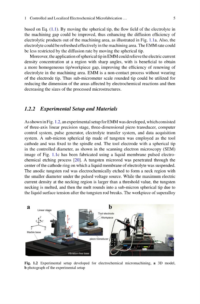
As shown in Fig. 1.2, an experimental setup for EMM was developed, which consisted
of three-axis linear precision stage, three-dimensional piezo transducer, computer
control system, pulse generator, electrolyte transfer system, and data acquisition
system. A sub-micron spherical tip made of tungsten was employed as the tool
cathode and was fixed to the spindle end. The tool electrode with a spherical tip
in the controlled diameter, as shown in the scanning electron microscopy (SEM)
image of Fig. 1.1c has been fabricated using a liquid membrane pulsed electrochemical etching process [20]. A tungsten microrod was penetrated through the
center of the cathode ring on which a liquid membrane of electrolyte was suspended.
The anodic tungsten rod was electrochemically etched to form a neck region with
the smaller diameter under the pulsed voltage source. While the maximum electric
current density at the necking region is larger than a threshold value, the tungsten
necking is melted, and then the melt rounds into a sub-micron spherical tip due to
the liquid surface tension after the tungsten rod breaks. The workpiece of superalloy
Fig. 1.2 Experimental setup developed for electrochemical micromachining, a 3D model,
b photograph of the experimental setup
5
based on Eq. (1.1). By moving the spherical tip, the flow field of the electrolyte in
the machining gap could be improved, thus enhancing the diffusion efficiency of
electrolytic products out of the machining area, as illustrated in Fig. 1.1a. Also, the
electrolyte could be refreshed effectively in the machining area. The EMM rate could
be less restricted by the diffusion rate by moving the spherical tip.
Moreover, the application of spherical tip in EMM could relieve the electric current
density concentration at a region with sharp angles, with is beneficial to obtain
a more homogeneous tip/workpiece gap, improving the efficiency of renewing of
electrolyte in the machining area. EMM is a non-contact process without wearing
of the electrode tip. Thus sub-micrometer scale rounded tip could be utilized for
reducing the dimension of the areas affected by electrochemical reactions and then
decreasing the sizes of the processed microstructures.
1.2.2 Experimental Setup and Materials
As shown in Fig. 1.2, an experimental setup for EMM was developed, which consisted
of three-axis linear precision stage, three-dimensional piezo transducer, computer
control system, pulse generator, electrolyte transfer system, and data acquisition
system. A sub-micron spherical tip made of tungsten was employed as the tool
cathode and was fixed to the spindle end. The tool electrode with a spherical tip
in the controlled diameter, as shown in the scanning electron microscopy (SEM)
image of Fig. 1.1c has been fabricated using a liquid membrane pulsed electrochemical etching process [20]. A tungsten microrod was penetrated through the
center of the cathode ring on which a liquid membrane of electrolyte was suspended.
The anodic tungsten rod was electrochemically etched to form a neck region with
the smaller diameter under the pulsed voltage source. While the maximum electric
current density at the necking region is larger than a threshold value, the tungsten
necking is melted, and then the melt rounds into a sub-micron spherical tip due to
the liquid surface tension after the tungsten rod breaks. The workpiece of superalloy
Fig. 1.2 Experimental setup developed for electrochemical micromachining, a 3D model,
b photograph of the experimental setup