

11 Numerical and Experimental Study on Orthogonal …
137
It can be seen from the finite element simulation that the surface quality of the
chip bottom surface after “derivative cutting” is relatively good. The micro-pit array
can intercept debris and hard particles on the bottom surface of the chip, reduce the
scratching and furrowing effect of the chip bottom on the rake face, and improve
the surface quality of the chip bottom surface. It can be seen that the micro-pit
texture is conducive to chip breaking, reduces the formation of spiral chips, improves
the surface quality of the workpiece and the life of the cutting edge, the micro-pit
intercepts a small amount of debris and hard particles on the bottom of the chip, and
reduces the bottom face of the chip. The scratching of the surface and the furrow
effect of hard particles improve the friction and wear resistance of the tool.
11.3.2 Comparative Analysis of Cutting Force
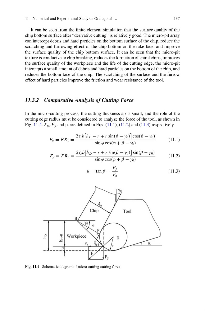
In the micro-cutting process, the cutting thickness ap is small, and the role of the
cutting edge radius must be considered to analyze the force of the tool, as shown in
Fig. 11.4. F x , F y and µ are defined in Eqs. (11.1), (11.2) and (11.3) respectively.
F x = F R 1 =
2τ s b
h D − r + r sin(β − γ 0 )
cos(β − γ 0 )
sin ϕ cos(ϕ + β − γ 0 )
(11.1)
F y = F R 2 =
2τ s b
h D − r + r sin(β − γ 0 )
sin(β − γ 0 )
sin ϕ cos(ϕ + β − γ 0 )
(11.2)
μ = tan β =
F f
F n
(11.3)
Fig. 11.4 Schematic diagram of micro-cutting cutting force
137
It can be seen from the finite element simulation that the surface quality of the
chip bottom surface after “derivative cutting” is relatively good. The micro-pit array
can intercept debris and hard particles on the bottom surface of the chip, reduce the
scratching and furrowing effect of the chip bottom on the rake face, and improve
the surface quality of the chip bottom surface. It can be seen that the micro-pit
texture is conducive to chip breaking, reduces the formation of spiral chips, improves
the surface quality of the workpiece and the life of the cutting edge, the micro-pit
intercepts a small amount of debris and hard particles on the bottom of the chip, and
reduces the bottom face of the chip. The scratching of the surface and the furrow
effect of hard particles improve the friction and wear resistance of the tool.
11.3.2 Comparative Analysis of Cutting Force
In the micro-cutting process, the cutting thickness ap is small, and the role of the
cutting edge radius must be considered to analyze the force of the tool, as shown in
Fig. 11.4. F x , F y and µ are defined in Eqs. (11.1), (11.2) and (11.3) respectively.
F x = F R 1 =
2τ s b
h D − r + r sin(β − γ 0 )
cos(β − γ 0 )
sin ϕ cos(ϕ + β − γ 0 )
(11.1)
F y = F R 2 =
2τ s b
h D − r + r sin(β − γ 0 )
sin(β − γ 0 )
sin ϕ cos(ϕ + β − γ 0 )
(11.2)
μ = tan β =
F f
F n
(11.3)
Fig. 11.4 Schematic diagram of micro-cutting cutting force