

138
Q.-Q. Cai et al.
In above equations, τ s is the shear stress on the shear plane, b is the cutting width,
r is the cutting edge radius, γ 0 is the tool rake angle, β is the friction angle, andϕ
is the shear angle; F n is the positive pressure on the rake face, and F f is the friction
force on the rake face. When γ 0 = 0, you can obtain Eq. (11.4):
μ = tan β =
F f
F n
=
F y
F x
=
F R 2
F R 1
(11.4)
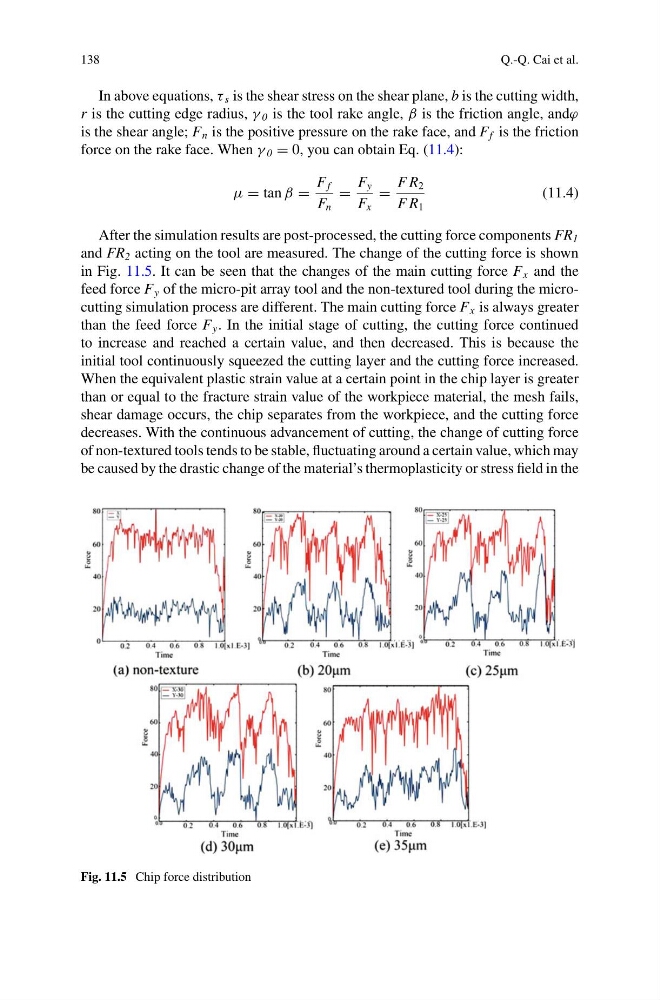
After the simulation results are post-processed, the cutting force components FR 1
and FR 2 acting on the tool are measured. The change of the cutting force is shown
in Fig. 11.5. It can be seen that the changes of the main cutting force F x and the
feed force F y of the micro-pit array tool and the non-textured tool during the microcutting simulation process are different. The main cutting force F x is always greater
than the feed force F y . In the initial stage of cutting, the cutting force continued
to increase and reached a certain value, and then decreased. This is because the
initial tool continuously squeezed the cutting layer and the cutting force increased.
When the equivalent plastic strain value at a certain point in the chip layer is greater
than or equal to the fracture strain value of the workpiece material, the mesh fails,
shear damage occurs, the chip separates from the workpiece, and the cutting force
decreases. With the continuous advancement of cutting, the change of cutting force
of non-textured tools tends to be stable, fluctuating around a certain value, which may
be caused by the drastic change of the material’s thermoplasticity or stress field in the
Fig. 11.5 Chip force distribution
Q.-Q. Cai et al.
In above equations, τ s is the shear stress on the shear plane, b is the cutting width,
r is the cutting edge radius, γ 0 is the tool rake angle, β is the friction angle, andϕ
is the shear angle; F n is the positive pressure on the rake face, and F f is the friction
force on the rake face. When γ 0 = 0, you can obtain Eq. (11.4):
μ = tan β =
F f
F n
=
F y
F x
=
F R 2
F R 1
(11.4)
After the simulation results are post-processed, the cutting force components FR 1
and FR 2 acting on the tool are measured. The change of the cutting force is shown
in Fig. 11.5. It can be seen that the changes of the main cutting force F x and the
feed force F y of the micro-pit array tool and the non-textured tool during the microcutting simulation process are different. The main cutting force F x is always greater
than the feed force F y . In the initial stage of cutting, the cutting force continued
to increase and reached a certain value, and then decreased. This is because the
initial tool continuously squeezed the cutting layer and the cutting force increased.
When the equivalent plastic strain value at a certain point in the chip layer is greater
than or equal to the fracture strain value of the workpiece material, the mesh fails,
shear damage occurs, the chip separates from the workpiece, and the cutting force
decreases. With the continuous advancement of cutting, the change of cutting force
of non-textured tools tends to be stable, fluctuating around a certain value, which may
be caused by the drastic change of the material’s thermoplasticity or stress field in the
Fig. 11.5 Chip force distribution