

136
Q.-Q. Cai et al.
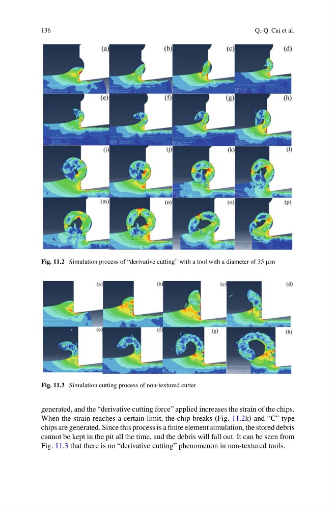
Fig. 11.2 Simulation process of “derivative cutting” with a tool with a diameter of 35 µm
Fig. 11.3 Simulation cutting process of non-textured cutter
generated, and the “derivative cutting force” applied increases the strain of the chips.
When the strain reaches a certain limit, the chip breaks (Fig. 11.2k) and “C” type
chips are generated. Since this process is a finite element simulation, the stored debris
cannot be kept in the pit all the time, and the debris will fall out. It can be seen from
Fig. 11.3 that there is no “derivative cutting” phenomenon in non-textured tools.
Q.-Q. Cai et al.
Fig. 11.2 Simulation process of “derivative cutting” with a tool with a diameter of 35 µm
Fig. 11.3 Simulation cutting process of non-textured cutter
generated, and the “derivative cutting force” applied increases the strain of the chips.
When the strain reaches a certain limit, the chip breaks (Fig. 11.2k) and “C” type
chips are generated. Since this process is a finite element simulation, the stored debris
cannot be kept in the pit all the time, and the debris will fall out. It can be seen from
Fig. 11.3 that there is no “derivative cutting” phenomenon in non-textured tools.