

11 Numerical and Experimental Study on Orthogonal …
135
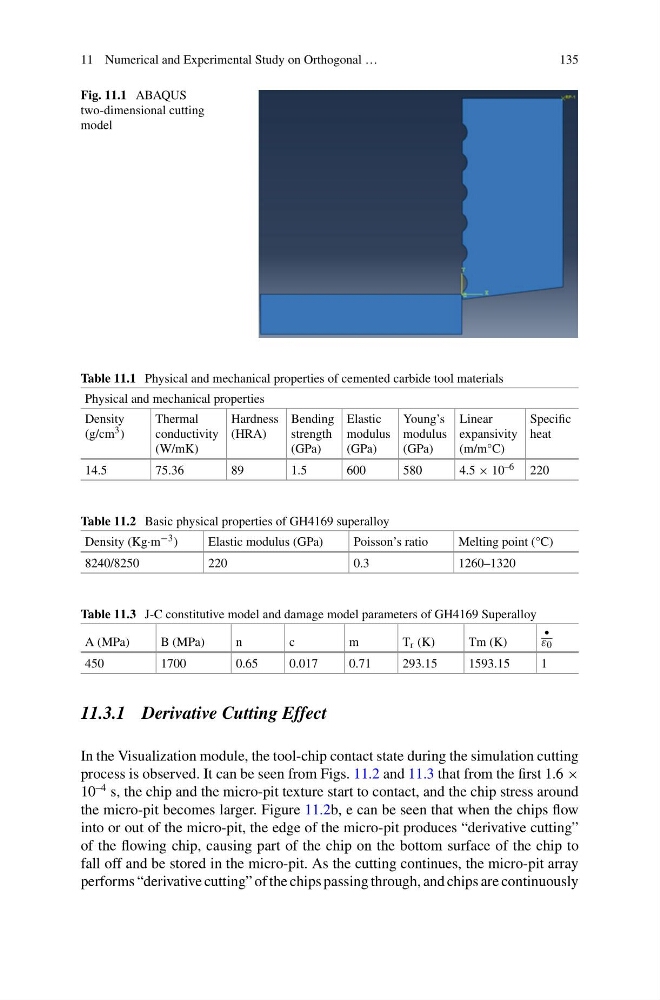
Fig. 11.1 ABAQUS
two-dimensional cutting
model
Table 11.1 Physical and mechanical properties of cemented carbide tool materials
Physical and mechanical properties
Density
(g/cm 3 )
Thermal
conductivity
(W/mK)
Hardness
(HRA)
Bending
strength
(GPa)
Elastic
modulus
(GPa)
Young’s
modulus
(GPa)
Linear
expansivity
(m/m°C)
Specific
heat
14.5
75.36
89
1.5
600
580
4.5 × 10 –6 220
Table 11.2 Basic physical properties of GH4169 superalloy
Density (Kg·m −3 )
Elastic modulus (GPa)
Poisson’s ratio
Melting point (°C)
8240/8250
220
0.3
1260–1320
Table 11.3 J-C constitutive model and damage model parameters of GH4169 Superalloy
A (MPa)
B (MPa)
n
c
m
T r (K)
Tm (K)
•
ε 0
450
1700
0.65
0.017
0.71
293.15
1593.15
1
11.3.1 Derivative Cutting Effect
In the Visualization module, the tool-chip contact state during the simulation cutting
process is observed. It can be seen from Figs. 11.2 and 11.3 that from the first 1.6 ×
10
–4 s, the chip and the micro-pit texture start to contact, and the chip stress around
the micro-pit becomes larger. Figure 11.2b, e can be seen that when the chips flow
into or out of the micro-pit, the edge of the micro-pit produces “derivative cutting”
of the flowing chip, causing part of the chip on the bottom surface of the chip to
fall off and be stored in the micro-pit. As the cutting continues, the micro-pit array
performs “derivative cutting” of the chips passing through, and chips are continuously
135
Fig. 11.1 ABAQUS
two-dimensional cutting
model
Table 11.1 Physical and mechanical properties of cemented carbide tool materials
Physical and mechanical properties
Density
(g/cm 3 )
Thermal
conductivity
(W/mK)
Hardness
(HRA)
Bending
strength
(GPa)
Elastic
modulus
(GPa)
Young’s
modulus
(GPa)
Linear
expansivity
(m/m°C)
Specific
heat
14.5
75.36
89
1.5
600
580
4.5 × 10 –6 220
Table 11.2 Basic physical properties of GH4169 superalloy
Density (Kg·m −3 )
Elastic modulus (GPa)
Poisson’s ratio
Melting point (°C)
8240/8250
220
0.3
1260–1320
Table 11.3 J-C constitutive model and damage model parameters of GH4169 Superalloy
A (MPa)
B (MPa)
n
c
m
T r (K)
Tm (K)
•
ε 0
450
1700
0.65
0.017
0.71
293.15
1593.15
1
11.3.1 Derivative Cutting Effect
In the Visualization module, the tool-chip contact state during the simulation cutting
process is observed. It can be seen from Figs. 11.2 and 11.3 that from the first 1.6 ×
10
–4 s, the chip and the micro-pit texture start to contact, and the chip stress around
the micro-pit becomes larger. Figure 11.2b, e can be seen that when the chips flow
into or out of the micro-pit, the edge of the micro-pit produces “derivative cutting”
of the flowing chip, causing part of the chip on the bottom surface of the chip to
fall off and be stored in the micro-pit. As the cutting continues, the micro-pit array
performs “derivative cutting” of the chips passing through, and chips are continuously