

120
Y. Ge and Z. Ye
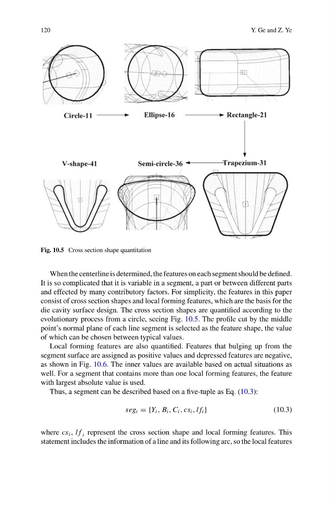
Fig. 10.5 Cross section shape quantitation
When the centerline is determined, the features on each segment should be defined.
It is so complicated that it is variable in a segment, a part or between different parts
and effected by many contributory factors. For simplicity, the features in this paper
consist of cross section shapes and local forming features, which are the basis for the
die cavity surface design. The cross section shapes are quantified according to the
evolutionary process from a circle, seeing Fig. 10.5. The profile cut by the middle
point’s normal plane of each line segment is selected as the feature shape, the value
of which can be chosen between typical values.
Local forming features are also quantified. Features that bulging up from the
segment surface are assigned as positive values and depressed features are negative,
as shown in Fig. 10.6. The inner values are available based on actual situations as
well. For a segment that contains more than one local forming features, the feature
with largest absolute value is used.
Thus, a segment can be described based on a five-tuple as Eq. (10.3):
seg i = {Y i , B i , C i , cs i , l f i }
(10.3)
where cs i , l f i represent the cross section shape and local forming features. This
statement includes the information of a line and its following arc, so the local features
Y. Ge and Z. Ye
Fig. 10.5 Cross section shape quantitation
When the centerline is determined, the features on each segment should be defined.
It is so complicated that it is variable in a segment, a part or between different parts
and effected by many contributory factors. For simplicity, the features in this paper
consist of cross section shapes and local forming features, which are the basis for the
die cavity surface design. The cross section shapes are quantified according to the
evolutionary process from a circle, seeing Fig. 10.5. The profile cut by the middle
point’s normal plane of each line segment is selected as the feature shape, the value
of which can be chosen between typical values.
Local forming features are also quantified. Features that bulging up from the
segment surface are assigned as positive values and depressed features are negative,
as shown in Fig. 10.6. The inner values are available based on actual situations as
well. For a segment that contains more than one local forming features, the feature
with largest absolute value is used.
Thus, a segment can be described based on a five-tuple as Eq. (10.3):
seg i = {Y i , B i , C i , cs i , l f i }
(10.3)
where cs i , l f i represent the cross section shape and local forming features. This
statement includes the information of a line and its following arc, so the local features