

10 Tube Hydro-Forming Process Design Based …
119
where t i is the initial blank thickness, and RC min is the minimum fillet radius of part
and σ b is the ultimate strength stress of material.
When the process and layout of die planning completed, the feasibility of the
part should be evaluated to obtain the process parameters to which the maximum
expansion and material parameters are particularly critical. The maximum expansion
indicates the formability of the part and the axial feed amount. The initial pressure
of hydro-forming process can be calculated by Eq. (10.2):
p =
2t i σ s
d 0 − t i
(10.2)
where d 0 the outer diameter and σ s is the yielding stress. Then the loading path should
be optimized for a better forming quality.
The purpose of the featured-based representation is to categorize a particular part
into different segments to build the bridge between the geometry design and the
manufacturing. The most important feature of a tubular part is the centerline with
which it can be recognized with a list of segments with features on them. In this work,
the centerline is represented in an incremental YBC coordinate which is widely used
in tube NC bending process [12]. A spatial bent tube contains a list of three-tuples
that feeding, rotating and bending whose bending radius is usually a constant. Thus,
normal planes on the points of tangency can cut the part into segments naturally.
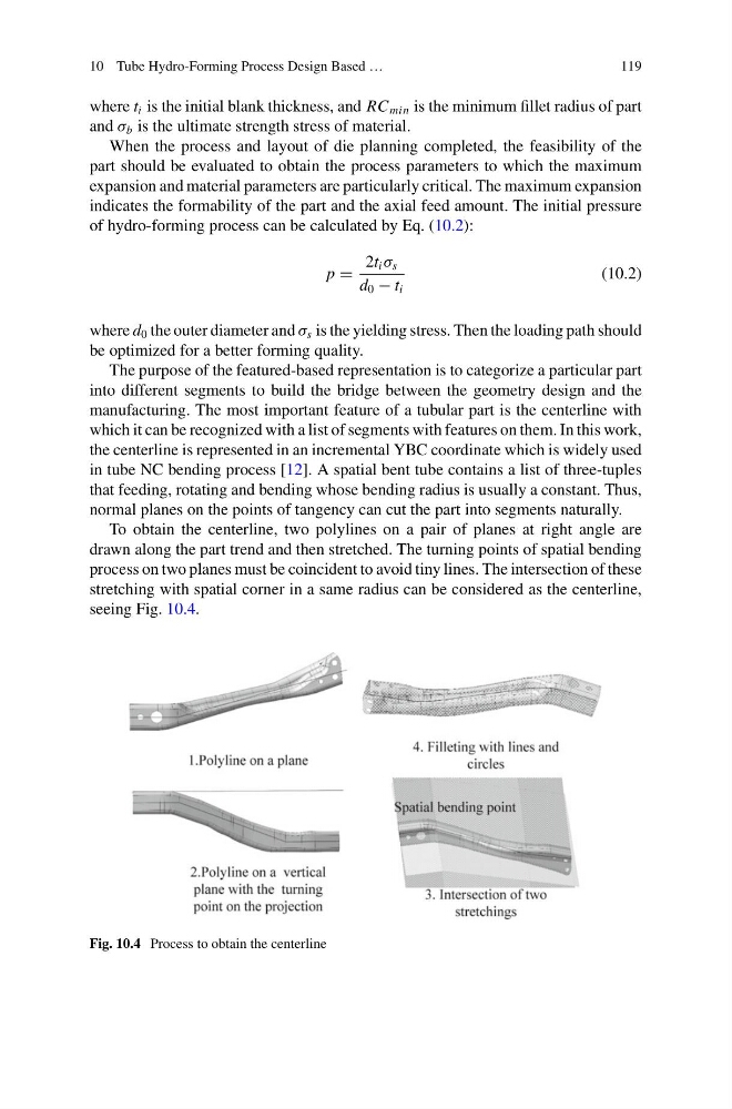
To obtain the centerline, two polylines on a pair of planes at right angle are
drawn along the part trend and then stretched. The turning points of spatial bending
process on two planes must be coincident to avoid tiny lines. The intersection of these
stretching with spatial corner in a same radius can be considered as the centerline,
seeing Fig. 10.4.
Fig. 10.4 Process to obtain the centerline
119
where t i is the initial blank thickness, and RC min is the minimum fillet radius of part
and σ b is the ultimate strength stress of material.
When the process and layout of die planning completed, the feasibility of the
part should be evaluated to obtain the process parameters to which the maximum
expansion and material parameters are particularly critical. The maximum expansion
indicates the formability of the part and the axial feed amount. The initial pressure
of hydro-forming process can be calculated by Eq. (10.2):
p =
2t i σ s
d 0 − t i
(10.2)
where d 0 the outer diameter and σ s is the yielding stress. Then the loading path should
be optimized for a better forming quality.
The purpose of the featured-based representation is to categorize a particular part
into different segments to build the bridge between the geometry design and the
manufacturing. The most important feature of a tubular part is the centerline with
which it can be recognized with a list of segments with features on them. In this work,
the centerline is represented in an incremental YBC coordinate which is widely used
in tube NC bending process [12]. A spatial bent tube contains a list of three-tuples
that feeding, rotating and bending whose bending radius is usually a constant. Thus,
normal planes on the points of tangency can cut the part into segments naturally.
To obtain the centerline, two polylines on a pair of planes at right angle are
drawn along the part trend and then stretched. The turning points of spatial bending
process on two planes must be coincident to avoid tiny lines. The intersection of these
stretching with spatial corner in a same radius can be considered as the centerline,
seeing Fig. 10.4.
Fig. 10.4 Process to obtain the centerline