

18
1 Modeling Systems
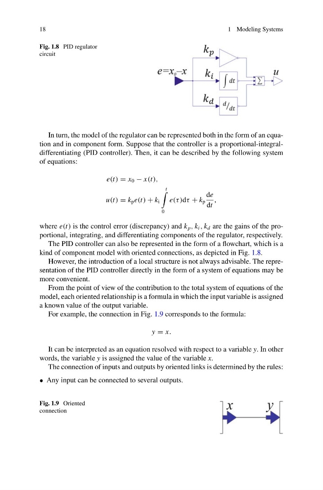
Fig. 1.8 PID regulator
circuit
In turn, the model of the regulator can be represented both in the form of an equation and in component form. Suppose that the controller is a proportional-integraldifferentiating (PID controller). Then, it can be described by the following system
of equations:
e(t) = x 0 − x(t),
u(t) = k p e(t) + k i
t
0
e(τ )dτ + k p
de
dt
,
where e(t) is the control error (discrepancy) and k p , k i , k d are the gains of the proportional, integrating, and differentiating components of the regulator, respectively.
The PID controller can also be represented in the form of a flowchart, which is a
kind of component model with oriented connections, as depicted in Fig. 1.8.
However, the introduction of a local structure is not always advisable. The representation of the PID controller directly in the form of a system of equations may be
more convenient.
From the point of view of the contribution to the total system of equations of the
model, each oriented relationship is a formula in which the input variable is assigned
a known value of the output variable.
For example, the connection in Fig. 1.9 corresponds to the formula:
y = x.
It can be interpreted as an equation resolved with respect to a variable y. In other
words, the variable y is assigned the value of the variable x.
The connection of inputs and outputs by oriented links is determined by the rules:
• Any input can be connected to several outputs.
Fig. 1.9 Oriented
connection
1 Modeling Systems
Fig. 1.8 PID regulator
circuit
In turn, the model of the regulator can be represented both in the form of an equation and in component form. Suppose that the controller is a proportional-integraldifferentiating (PID controller). Then, it can be described by the following system
of equations:
e(t) = x 0 − x(t),
u(t) = k p e(t) + k i
t
0
e(τ )dτ + k p
de
dt
,
where e(t) is the control error (discrepancy) and k p , k i , k d are the gains of the proportional, integrating, and differentiating components of the regulator, respectively.
The PID controller can also be represented in the form of a flowchart, which is a
kind of component model with oriented connections, as depicted in Fig. 1.8.
However, the introduction of a local structure is not always advisable. The representation of the PID controller directly in the form of a system of equations may be
more convenient.
From the point of view of the contribution to the total system of equations of the
model, each oriented relationship is a formula in which the input variable is assigned
a known value of the output variable.
For example, the connection in Fig. 1.9 corresponds to the formula:
y = x.
It can be interpreted as an equation resolved with respect to a variable y. In other
words, the variable y is assigned the value of the variable x.
The connection of inputs and outputs by oriented links is determined by the rules:
• Any input can be connected to several outputs.
Fig. 1.9 Oriented
connection