

1.10 Component-Oriented Approach in Modeling
19
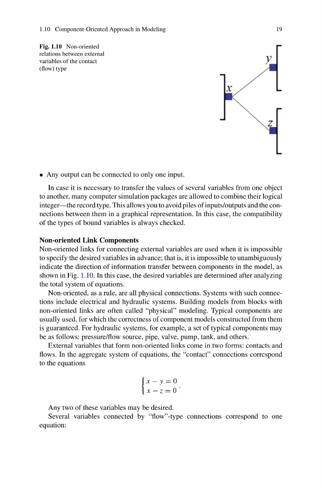
Fig. 1.10 Non-oriented
relations between external
variables of the contact
(flow) type
• Any output can be connected to only one input.
In case it is necessary to transfer the values of several variables from one object
to another, many computer simulation packages are allowed to combine their logical
integer—the record type. This allows you to avoid piles of inputs/outputs and the connections between them in a graphical representation. In this case, the compatibility
of the types of bound variables is always checked.
Non-oriented Link Components
Non-oriented links for connecting external variables are used when it is impossible
to specify the desired variables in advance; that is, it is impossible to unambiguously
indicate the direction of information transfer between components in the model, as
shown in Fig. 1.10. In this case, the desired variables are determined after analyzing
the total system of equations.
Non-oriented, as a rule, are all physical connections. Systems with such connections include electrical and hydraulic systems. Building models from blocks with
non-oriented links are often called “physical” modeling. Typical components are
usually used, for which the correctness of component models constructed from them
is guaranteed. For hydraulic systems, for example, a set of typical components may
be as follows: pressure/flow source, pipe, valve, pump, tank, and others.
External variables that form non-oriented links come in two forms: contacts and
flows. In the aggregate system of equations, the “contact” connections correspond
to the equations
x − y = 0
x − z = 0
.
Any two of these variables may be desired.
Several variables connected by “flow”-type connections correspond to one
equation:
19
Fig. 1.10 Non-oriented
relations between external
variables of the contact
(flow) type
• Any output can be connected to only one input.
In case it is necessary to transfer the values of several variables from one object
to another, many computer simulation packages are allowed to combine their logical
integer—the record type. This allows you to avoid piles of inputs/outputs and the connections between them in a graphical representation. In this case, the compatibility
of the types of bound variables is always checked.
Non-oriented Link Components
Non-oriented links for connecting external variables are used when it is impossible
to specify the desired variables in advance; that is, it is impossible to unambiguously
indicate the direction of information transfer between components in the model, as
shown in Fig. 1.10. In this case, the desired variables are determined after analyzing
the total system of equations.
Non-oriented, as a rule, are all physical connections. Systems with such connections include electrical and hydraulic systems. Building models from blocks with
non-oriented links are often called “physical” modeling. Typical components are
usually used, for which the correctness of component models constructed from them
is guaranteed. For hydraulic systems, for example, a set of typical components may
be as follows: pressure/flow source, pipe, valve, pump, tank, and others.
External variables that form non-oriented links come in two forms: contacts and
flows. In the aggregate system of equations, the “contact” connections correspond
to the equations
x − y = 0
x − z = 0
.
Any two of these variables may be desired.
Several variables connected by “flow”-type connections correspond to one
equation: