

216
6 Hierarchical Component Models
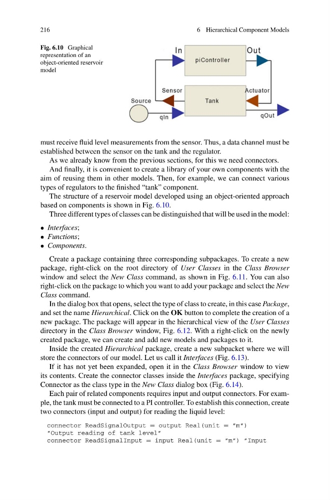
Fig. 6.10 Graphical
representation of an
object-oriented reservoir
model
must receive fluid level measurements from the sensor. Thus, a data channel must be
established between the sensor on the tank and the regulator.
As we already know from the previous sections, for this we need connectors.
And finally, it is convenient to create a library of your own components with the
aim of reusing them in other models. Then, for example, we can connect various
types of regulators to the finished “tank” component.
The structure of a reservoir model developed using an object-oriented approach
based on components is shown in Fig. 6.10.
Three different types of classes can be distinguished that will be used in the model:
• Interfaces;
• Functions;
• Components.
Create a package containing three corresponding subpackages. To create a new
package, right-click on the root directory of User Classes in the Class Browser
window and select the New Class command, as shown in Fig. 6.11. You can also
right-click on the package to which you want to add your package and select the New
Class command.
In the dialog box that opens, select the type of class to create, in this case Package,
and set the name Hierarchical. Click on the OK button to complete the creation of a
new package. The package will appear in the hierarchical view of the User Classes
directory in the Class Browser window, Fig. 6.12. With a right-click on the newly
created package, we can create and add new models and packages to it.
Inside the created Hierarchical package, create a new subpacket where we will
store the connectors of our model. Let us call it Interfaces (Fig. 6.13).
If it has not yet been expanded, open it in the Class Browser window to view
its contents. Create the connector classes inside the Interfaces package, specifying
Connector as the class type in the New Class dialog box (Fig. 6.14).
Each pair of related components requires input and output connectors. For example, the tank must be connected to a PI controller. To establish this connection, create
two connectors (input and output) for reading the liquid level:
connector ReadSignalOutput = output Real(unit = ”m”)
”Output reading of tank level”
connector ReadSignalInput = input Real(unit = ”m”) ”Input
6 Hierarchical Component Models
Fig. 6.10 Graphical
representation of an
object-oriented reservoir
model
must receive fluid level measurements from the sensor. Thus, a data channel must be
established between the sensor on the tank and the regulator.
As we already know from the previous sections, for this we need connectors.
And finally, it is convenient to create a library of your own components with the
aim of reusing them in other models. Then, for example, we can connect various
types of regulators to the finished “tank” component.
The structure of a reservoir model developed using an object-oriented approach
based on components is shown in Fig. 6.10.
Three different types of classes can be distinguished that will be used in the model:
• Interfaces;
• Functions;
• Components.
Create a package containing three corresponding subpackages. To create a new
package, right-click on the root directory of User Classes in the Class Browser
window and select the New Class command, as shown in Fig. 6.11. You can also
right-click on the package to which you want to add your package and select the New
Class command.
In the dialog box that opens, select the type of class to create, in this case Package,
and set the name Hierarchical. Click on the OK button to complete the creation of a
new package. The package will appear in the hierarchical view of the User Classes
directory in the Class Browser window, Fig. 6.12. With a right-click on the newly
created package, we can create and add new models and packages to it.
Inside the created Hierarchical package, create a new subpacket where we will
store the connectors of our model. Let us call it Interfaces (Fig. 6.13).
If it has not yet been expanded, open it in the Class Browser window to view
its contents. Create the connector classes inside the Interfaces package, specifying
Connector as the class type in the New Class dialog box (Fig. 6.14).
Each pair of related components requires input and output connectors. For example, the tank must be connected to a PI controller. To establish this connection, create
two connectors (input and output) for reading the liquid level:
connector ReadSignalOutput = output Real(unit = ”m”)
”Output reading of tank level”
connector ReadSignalInput = input Real(unit = ”m”) ”Input