

6.1 Draining of a Tank
215
Fig. 6.8 Hierarchical structure of the created FlatTank model
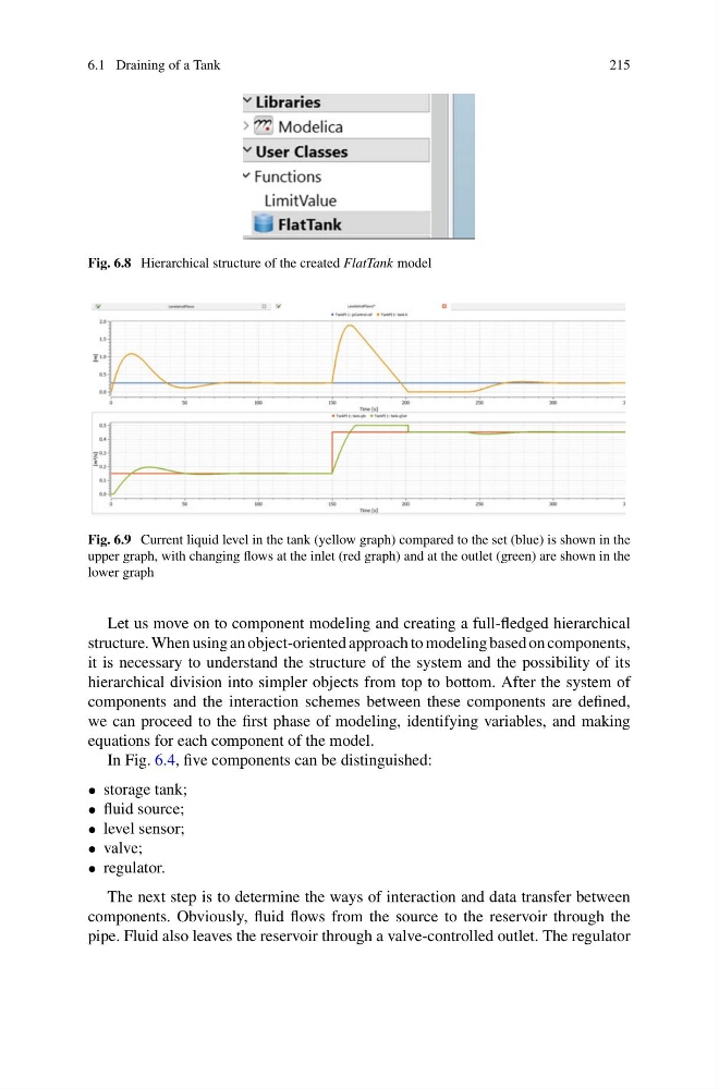
Fig. 6.9 Current liquid level in the tank (yellow graph) compared to the set (blue) is shown in the
upper graph, with changing flows at the inlet (red graph) and at the outlet (green) are shown in the
lower graph
Let us move on to component modeling and creating a full-fledged hierarchical
structure. When using an object-oriented approach to modeling based on components,
it is necessary to understand the structure of the system and the possibility of its
hierarchical division into simpler objects from top to bottom. After the system of
components and the interaction schemes between these components are defined,
we can proceed to the first phase of modeling, identifying variables, and making
equations for each component of the model.
In Fig. 6.4, five components can be distinguished:
• storage tank;
• fluid source;
• level sensor;
• valve;
• regulator.
The next step is to determine the ways of interaction and data transfer between
components. Obviously, fluid flows from the source to the reservoir through the
pipe. Fluid also leaves the reservoir through a valve-controlled outlet. The regulator
215
Fig. 6.8 Hierarchical structure of the created FlatTank model
Fig. 6.9 Current liquid level in the tank (yellow graph) compared to the set (blue) is shown in the
upper graph, with changing flows at the inlet (red graph) and at the outlet (green) are shown in the
lower graph
Let us move on to component modeling and creating a full-fledged hierarchical
structure. When using an object-oriented approach to modeling based on components,
it is necessary to understand the structure of the system and the possibility of its
hierarchical division into simpler objects from top to bottom. After the system of
components and the interaction schemes between these components are defined,
we can proceed to the first phase of modeling, identifying variables, and making
equations for each component of the model.
In Fig. 6.4, five components can be distinguished:
• storage tank;
• fluid source;
• level sensor;
• valve;
• regulator.
The next step is to determine the ways of interaction and data transfer between
components. Obviously, fluid flows from the source to the reservoir through the
pipe. Fluid also leaves the reservoir through a valve-controlled outlet. The regulator