

5.7 Gear Rotary Mechanical System
187
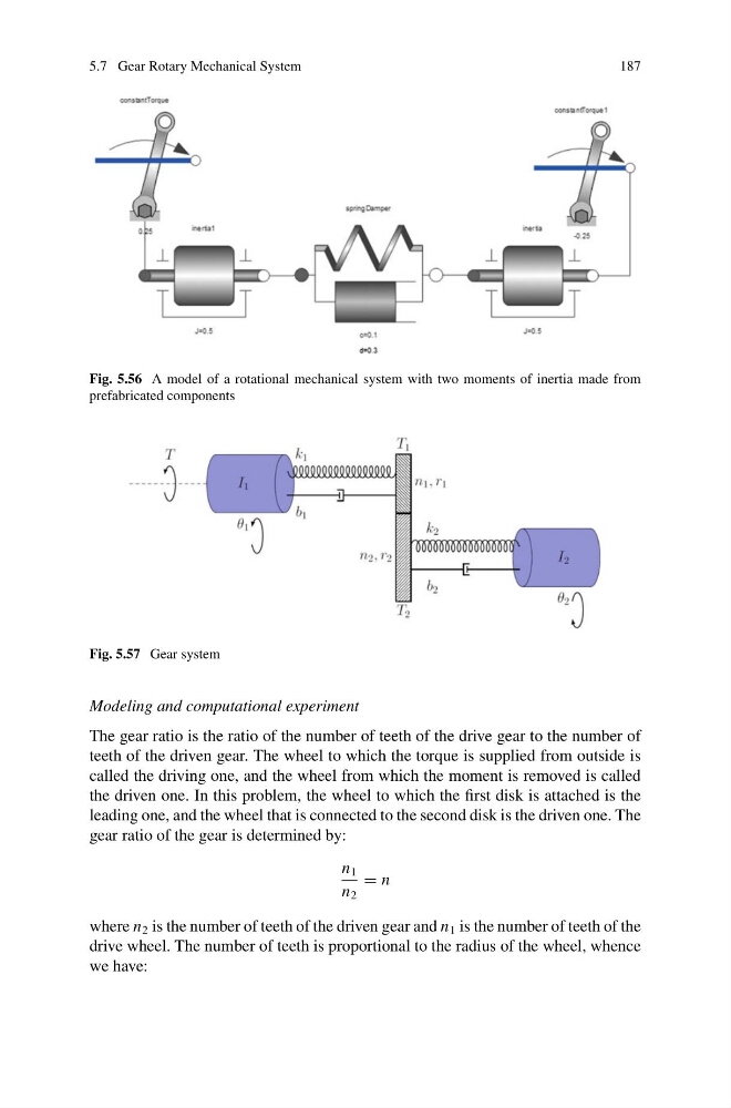
Fig. 5.56 A model of a rotational mechanical system with two moments of inertia made from
prefabricated components
Fig. 5.57 Gear system
Modeling and computational experiment
The gear ratio is the ratio of the number of teeth of the drive gear to the number of
teeth of the driven gear. The wheel to which the torque is supplied from outside is
called the driving one, and the wheel from which the moment is removed is called
the driven one. In this problem, the wheel to which the first disk is attached is the
leading one, and the wheel that is connected to the second disk is the driven one. The
gear ratio of the gear is determined by:
n 1
n 2
= n
where n 2 is the number of teeth of the driven gear and n 1 is the number of teeth of the
drive wheel. The number of teeth is proportional to the radius of the wheel, whence
we have:
187
Fig. 5.56 A model of a rotational mechanical system with two moments of inertia made from
prefabricated components
Fig. 5.57 Gear system
Modeling and computational experiment
The gear ratio is the ratio of the number of teeth of the drive gear to the number of
teeth of the driven gear. The wheel to which the torque is supplied from outside is
called the driving one, and the wheel from which the moment is removed is called
the driven one. In this problem, the wheel to which the first disk is attached is the
leading one, and the wheel that is connected to the second disk is the driven one. The
gear ratio of the gear is determined by:
n 1
n 2
= n
where n 2 is the number of teeth of the driven gear and n 1 is the number of teeth of the
drive wheel. The number of teeth is proportional to the radius of the wheel, whence
we have: