

144
4 Modeling of Mechanical Oscillatory Systems with One Degree …
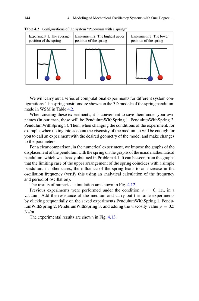
Table 4.2 Configurations of the system “Pendulum with a spring”
Experiment 1. The average
position of the spring
Experiment 2. The highest upper
position of the spring
Experiment 3. The lower
position of the spring
We will carry out a series of computational experiments for different system configurations. The spring positions are shown on the 3D models of the spring pendulum
made in WSM in Table 4.2.
When creating these experiments, it is convenient to save them under your own
names (in our case, these will be PendulumWithSpring 1, PendulumWithSpring 2,
PendulumWithSpring 3). Then, when changing the conditions of the experiment, for
example, when taking into account the viscosity of the medium, it will be enough for
you to call an experiment with the desired geometry of the model and make changes
to the parameters.
For a clear comparison, in the numerical experiment, we impose the graphs of the
displacement of the pendulum with the spring on the graphs of the usual mathematical
pendulum, which we already obtained in Problem 4.1. It can be seen from the graphs
that the limiting case of the upper arrangement of the spring coincides with a simple
pendulum, in other cases, the influence of the spring leads to an increase in the
oscillation frequency (verify this using an analytical calculation of the frequency
and period of oscillation).
The results of numerical simulation are shown in Fig. 4.12.
Previous experiments were performed under the condition γ = 0, i.e., in a
vacuum. Add the resistance of the medium and carry out the same experiments
by clicking sequentially on the saved experiments PendulumWithSpring 1, PendulumWithSpring 2, PendulumWithSpring 3, and adding the viscosity value γ = 0.5
Ns/m.
The experimental results are shown in Fig. 4.13.
4 Modeling of Mechanical Oscillatory Systems with One Degree …
Table 4.2 Configurations of the system “Pendulum with a spring”
Experiment 1. The average
position of the spring
Experiment 2. The highest upper
position of the spring
Experiment 3. The lower
position of the spring
We will carry out a series of computational experiments for different system configurations. The spring positions are shown on the 3D models of the spring pendulum
made in WSM in Table 4.2.
When creating these experiments, it is convenient to save them under your own
names (in our case, these will be PendulumWithSpring 1, PendulumWithSpring 2,
PendulumWithSpring 3). Then, when changing the conditions of the experiment, for
example, when taking into account the viscosity of the medium, it will be enough for
you to call an experiment with the desired geometry of the model and make changes
to the parameters.
For a clear comparison, in the numerical experiment, we impose the graphs of the
displacement of the pendulum with the spring on the graphs of the usual mathematical
pendulum, which we already obtained in Problem 4.1. It can be seen from the graphs
that the limiting case of the upper arrangement of the spring coincides with a simple
pendulum, in other cases, the influence of the spring leads to an increase in the
oscillation frequency (verify this using an analytical calculation of the frequency
and period of oscillation).
The results of numerical simulation are shown in Fig. 4.12.
Previous experiments were performed under the condition γ = 0, i.e., in a
vacuum. Add the resistance of the medium and carry out the same experiments
by clicking sequentially on the saved experiments PendulumWithSpring 1, PendulumWithSpring 2, PendulumWithSpring 3, and adding the viscosity value γ = 0.5
Ns/m.
The experimental results are shown in Fig. 4.13.