

4.3 Mathematical Pendulum with Spring
145
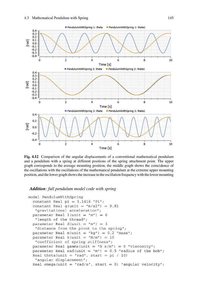
Fig. 4.12 Comparison of the angular displacements of a conventional mathematical pendulum
and a pendulum with a spring at different positions of the spring attachment point. The upper
graph corresponds to the average mounting position, the middle graph shows the coincidence of
the oscillations with the oscillations of the mathematical pendulum at the extreme upper mounting
position, and the lower graph shows the increase in the oscillation frequency with the lower mounting
Addition: full pendulum model code with spring
model PendulumWithSpring
constant Real pi = 3.1416 ”Pi”;
constant Real g(unit = ”m/s2”) = 9.81
”gravitational acceleration”;
parameter Real l(unit = ”m”) = 6
”length of the thread”;
parameter Real d(unit = ”m”) = 3
”distance from the pivot to the spring”;
parameter Real m(unit = ”kg”) = 0.2 ”mass”;
parameter Real k(unit = ”N/m”) = 10
”coefficient of spring stiffness”;
parameter Real gamma(unit = ”N s/m”) = 0 ”viscosity”;
parameter Real rad(unit = ”m”) = 0.5 ”radius of the bob”;
Real theta(unit = ”rad”, start = pi / 10)
”angular displacement”;
Real omega(unit = ”rad/s”, start = 0) ”angular velocity”;
145
Fig. 4.12 Comparison of the angular displacements of a conventional mathematical pendulum
and a pendulum with a spring at different positions of the spring attachment point. The upper
graph corresponds to the average mounting position, the middle graph shows the coincidence of
the oscillations with the oscillations of the mathematical pendulum at the extreme upper mounting
position, and the lower graph shows the increase in the oscillation frequency with the lower mounting
Addition: full pendulum model code with spring
model PendulumWithSpring
constant Real pi = 3.1416 ”Pi”;
constant Real g(unit = ”m/s2”) = 9.81
”gravitational acceleration”;
parameter Real l(unit = ”m”) = 6
”length of the thread”;
parameter Real d(unit = ”m”) = 3
”distance from the pivot to the spring”;
parameter Real m(unit = ”kg”) = 0.2 ”mass”;
parameter Real k(unit = ”N/m”) = 10
”coefficient of spring stiffness”;
parameter Real gamma(unit = ”N s/m”) = 0 ”viscosity”;
parameter Real rad(unit = ”m”) = 0.5 ”radius of the bob”;
Real theta(unit = ”rad”, start = pi / 10)
”angular displacement”;
Real omega(unit = ”rad/s”, start = 0) ”angular velocity”;