

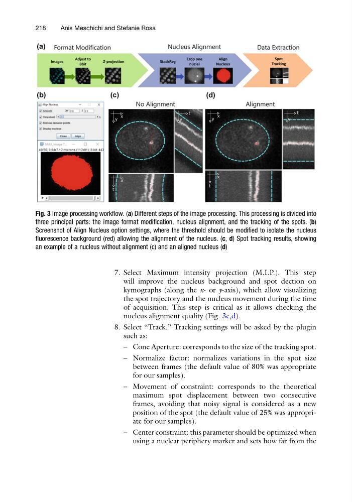
7. Select Maximum intensity projection (M.I.P.). This step
will improve the nucleus background and spot dection on
kymographs (along the x- or y-axis), which allow visualizing
the spot trajectory and the nucleus movement during the time
of acquisition. This step is critical as it allows checking the
nucleus alignment quality (Fig. 3c,d).
8. Select “Track.” Tracking settings will be asked by the plugin
such as:
– Cone Aperture: corresponds to the size of the tracking spot.
– Normalize factor: normalizes variations in the spot size
between frames (the default value of 80% was appropriate
for our samples).
– Movement of constraint: corresponds to the theoretical
maximum spot displacement between two consecutive
frames, avoiding that noisy signal is considered as a new
position of the spot (the default value of 25% was appropriate for our samples).
– Center constraint: this parameter should be optimized when
using a nuclear periphery marker and sets how far from the
Fig. 3 Image processing workflow. (a) Different steps of the image processing. This processing is divided into
three principal parts: the image format modification, nucleus alignment, and the tracking of the spots. (b)
Screenshot of Align Nucleus option settings, where the threshold should be modified to isolate the nucleus
fluorescence background (red) allowing the alignment of the nucleus. (c, d) Spot tracking results, showing
an example of a nucleus without alignment (c) and an aligned nucleus (d)
218
Anis Meschichi and Stefanie Rosa
will improve the nucleus background and spot dection on
kymographs (along the x- or y-axis), which allow visualizing
the spot trajectory and the nucleus movement during the time
of acquisition. This step is critical as it allows checking the
nucleus alignment quality (Fig. 3c,d).
8. Select “Track.” Tracking settings will be asked by the plugin
such as:
– Cone Aperture: corresponds to the size of the tracking spot.
– Normalize factor: normalizes variations in the spot size
between frames (the default value of 80% was appropriate
for our samples).
– Movement of constraint: corresponds to the theoretical
maximum spot displacement between two consecutive
frames, avoiding that noisy signal is considered as a new
position of the spot (the default value of 25% was appropriate for our samples).
– Center constraint: this parameter should be optimized when
using a nuclear periphery marker and sets how far from the
Fig. 3 Image processing workflow. (a) Different steps of the image processing. This processing is divided into
three principal parts: the image format modification, nucleus alignment, and the tracking of the spots. (b)
Screenshot of Align Nucleus option settings, where the threshold should be modified to isolate the nucleus
fluorescence background (red) allowing the alignment of the nucleus. (c, d) Spot tracking results, showing
an example of a nucleus without alignment (c) and an aligned nucleus (d)
218
Anis Meschichi and Stefanie Rosa