

measured per waveguide; in addition, PDMS optical waveguides of 8 cm length
were fabricated based on these different quality moulds. The optical insertion loss
of these PDMS waveguides obtained with different core–clad interface roughness
was measured at 850 nm wavelength. Compared with sidewall roughness, the top
and bottom interfaces between core and cladding can be neglected. Hereby, we
consider the interface roughness is mainly from the two sidewalls between them; in
addition, it is also assumed that the edge qualities of lines in every mask are
identical. Theoretically, the optical propagation loss due to scattering will be
increased evidently when average roughness of waveguide sidewalls is more than k
(wavelength)/20 [14], and hence to 850 nm wavelength, the critical transition
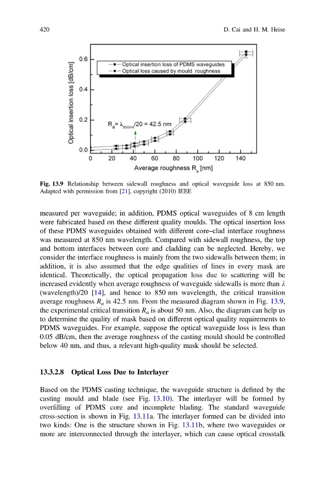
average roughness R a is 42.5 nm. From the measured diagram shown in Fig. 13.9,
the experimental critical transition R a is about 50 nm. Also, the diagram can help us
to determine the quality of mask based on different optical quality requirements to
PDMS waveguides. For example, suppose the optical waveguide loss is less than
0.05 dB/cm, then the average roughness of the casting mould should be controlled
below 40 nm, and thus, a relevant high-quality mask should be selected.
13.3.2.8 Optical Loss Due to Interlayer
Based on the PDMS casting technique, the waveguide structure is defined by the
casting mould and blade (see Fig. 13.10). The interlayer will be formed by
overfilling of PDMS core and incomplete blading. The standard waveguide
cross-section is shown in Fig. 13.11a. The interlayer formed can be divided into
two kinds: One is the structure shown in Fig. 13.11b, where two waveguides or
more are interconnected through the interlayer, which can cause optical crosstalk
Fig. 13.9 Relationship between sidewall roughness and optical waveguide loss at 850 nm.
Adapted with permission from [21], copyright (2010) IEEE
420
D. Cai and H. M. Heise
were fabricated based on these different quality moulds. The optical insertion loss
of these PDMS waveguides obtained with different core–clad interface roughness
was measured at 850 nm wavelength. Compared with sidewall roughness, the top
and bottom interfaces between core and cladding can be neglected. Hereby, we
consider the interface roughness is mainly from the two sidewalls between them; in
addition, it is also assumed that the edge qualities of lines in every mask are
identical. Theoretically, the optical propagation loss due to scattering will be
increased evidently when average roughness of waveguide sidewalls is more than k
(wavelength)/20 [14], and hence to 850 nm wavelength, the critical transition
average roughness R a is 42.5 nm. From the measured diagram shown in Fig. 13.9,
the experimental critical transition R a is about 50 nm. Also, the diagram can help us
to determine the quality of mask based on different optical quality requirements to
PDMS waveguides. For example, suppose the optical waveguide loss is less than
0.05 dB/cm, then the average roughness of the casting mould should be controlled
below 40 nm, and thus, a relevant high-quality mask should be selected.
13.3.2.8 Optical Loss Due to Interlayer
Based on the PDMS casting technique, the waveguide structure is defined by the
casting mould and blade (see Fig. 13.10). The interlayer will be formed by
overfilling of PDMS core and incomplete blading. The standard waveguide
cross-section is shown in Fig. 13.11a. The interlayer formed can be divided into
two kinds: One is the structure shown in Fig. 13.11b, where two waveguides or
more are interconnected through the interlayer, which can cause optical crosstalk
Fig. 13.9 Relationship between sidewall roughness and optical waveguide loss at 850 nm.
Adapted with permission from [21], copyright (2010) IEEE
420
D. Cai and H. M. Heise