

13.3.2.7 Scattering Loss from Mould Roughness
Besides the intrinsic scattering losses, core–clad interface roughness is another
source of extrinsic loss. Actually, except scattering loss, roughness and inhomogeneity can also generate unwanted mode coupling and modulation of mode coupling in devices and beating/coupling length. Thus, the extrinsic loss in a
waveguide system typically results from core–clad interface roughness, which
needs to be analysed. Referring to the casting method for PDMS waveguide fabrication, actually the interface roughness is the copy of grooves and defects from the
sidewalls of the casting moulds. Additional attenuation (scattering loss), which is
from continuous coupling from bound modes to the radiation field, may be caused
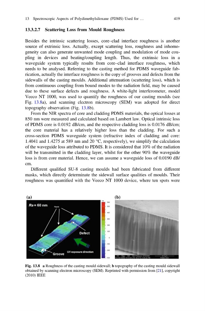
due to these surface defects and roughness. A white-light interferometer, model
Veeco NT 1000, was used to quantify the roughness of our casting moulds (see
Fig. 13.8a), and scanning electron microscopy (SEM) was adopted for direct
topography observation (Fig. 13.8b).
From the NIR spectra of core and cladding PDMS materials, the optical losses at
850 nm were measured and calculated based on Lambert law. Optical intrinsic loss
of PDMS core is 0.0192 dB/cm, and the respective cladding loss is 0.0176 dB/cm;
the core material has a relatively higher loss than the cladding. For such a
cross-section PDMS waveguide system (refractive index of cladding and core:
1.4041 and 1.4275 at 589 nm and 20 °C, respectively), we simplify the calculation
of the waveguide loss attributed to PDMS. It is considered that 10% of the radiation
will be transmitted in the cladding layer, whilst for the other 90% the waveguide
loss is from core material. Hence, we can assume a waveguide loss of 0.0190 dB/
cm.
Different qualified SU-8 casting moulds had been fabricated from different
masks, which directly determinate the sidewall surface qualities of moulds. Their
roughness was quantified with the Veeco NT 1000 device, where ten spots were
Fig. 13.8 a Roughness of the casting mould sidewall; b topography of the casting mould sidewall
obtained by scanning electron microscopy (SEM). Reprinted with permission from [21], copyright
(2010) IEEE
13 Spectroscopic Aspects of Polydimethylsiloxane (PDMS) Used for …
419
Besides the intrinsic scattering losses, core–clad interface roughness is another
source of extrinsic loss. Actually, except scattering loss, roughness and inhomogeneity can also generate unwanted mode coupling and modulation of mode coupling in devices and beating/coupling length. Thus, the extrinsic loss in a
waveguide system typically results from core–clad interface roughness, which
needs to be analysed. Referring to the casting method for PDMS waveguide fabrication, actually the interface roughness is the copy of grooves and defects from the
sidewalls of the casting moulds. Additional attenuation (scattering loss), which is
from continuous coupling from bound modes to the radiation field, may be caused
due to these surface defects and roughness. A white-light interferometer, model
Veeco NT 1000, was used to quantify the roughness of our casting moulds (see
Fig. 13.8a), and scanning electron microscopy (SEM) was adopted for direct
topography observation (Fig. 13.8b).
From the NIR spectra of core and cladding PDMS materials, the optical losses at
850 nm were measured and calculated based on Lambert law. Optical intrinsic loss
of PDMS core is 0.0192 dB/cm, and the respective cladding loss is 0.0176 dB/cm;
the core material has a relatively higher loss than the cladding. For such a
cross-section PDMS waveguide system (refractive index of cladding and core:
1.4041 and 1.4275 at 589 nm and 20 °C, respectively), we simplify the calculation
of the waveguide loss attributed to PDMS. It is considered that 10% of the radiation
will be transmitted in the cladding layer, whilst for the other 90% the waveguide
loss is from core material. Hence, we can assume a waveguide loss of 0.0190 dB/
cm.
Different qualified SU-8 casting moulds had been fabricated from different
masks, which directly determinate the sidewall surface qualities of moulds. Their
roughness was quantified with the Veeco NT 1000 device, where ten spots were
Fig. 13.8 a Roughness of the casting mould sidewall; b topography of the casting mould sidewall
obtained by scanning electron microscopy (SEM). Reprinted with permission from [21], copyright
(2010) IEEE
13 Spectroscopic Aspects of Polydimethylsiloxane (PDMS) Used for …
419