

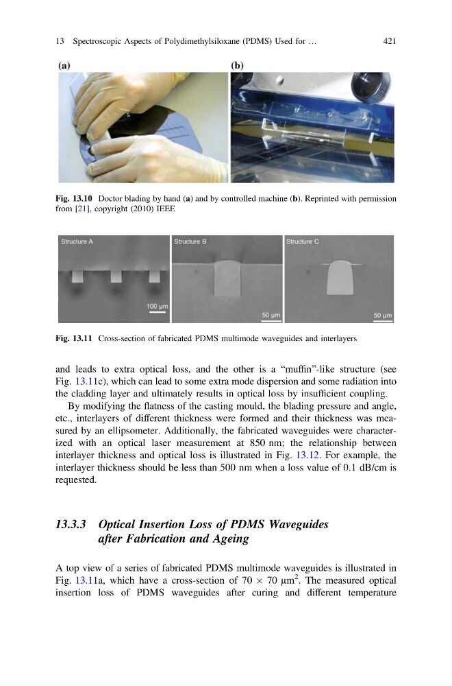
and leads to extra optical loss, and the other is a “muffin”-like structure (see
Fig. 13.11c), which can lead to some extra mode dispersion and some radiation into
the cladding layer and ultimately results in optical loss by insufficient coupling.
By modifying the flatness of the casting mould, the blading pressure and angle,
etc., interlayers of different thickness were formed and their thickness was measured by an ellipsometer. Additionally, the fabricated waveguides were characterized with an optical laser measurement at 850 nm; the relationship between
interlayer thickness and optical loss is illustrated in Fig. 13.12. For example, the
interlayer thickness should be less than 500 nm when a loss value of 0.1 dB/cm is
requested.
13.3.3 Optical Insertion Loss of PDMS Waveguides
after Fabrication and Ageing
A top view of a series of fabricated PDMS multimode waveguides is illustrated in
Fig. 13.11a, which have a cross-section of 70 Â 70 µm
2 . The measured optical
insertion loss of PDMS waveguides after curing and different temperature
Fig. 13.10 Doctor blading by hand (a) and by controlled machine (b). Reprinted with permission
from [21], copyright (2010) IEEE
Fig. 13.11 Cross-section of fabricated PDMS multimode waveguides and interlayers
13 Spectroscopic Aspects of Polydimethylsiloxane (PDMS) Used for …
421
Fig. 13.11c), which can lead to some extra mode dispersion and some radiation into
the cladding layer and ultimately results in optical loss by insufficient coupling.
By modifying the flatness of the casting mould, the blading pressure and angle,
etc., interlayers of different thickness were formed and their thickness was measured by an ellipsometer. Additionally, the fabricated waveguides were characterized with an optical laser measurement at 850 nm; the relationship between
interlayer thickness and optical loss is illustrated in Fig. 13.12. For example, the
interlayer thickness should be less than 500 nm when a loss value of 0.1 dB/cm is
requested.
13.3.3 Optical Insertion Loss of PDMS Waveguides
after Fabrication and Ageing
A top view of a series of fabricated PDMS multimode waveguides is illustrated in
Fig. 13.11a, which have a cross-section of 70 Â 70 µm
2 . The measured optical
insertion loss of PDMS waveguides after curing and different temperature
Fig. 13.10 Doctor blading by hand (a) and by controlled machine (b). Reprinted with permission
from [21], copyright (2010) IEEE
Fig. 13.11 Cross-section of fabricated PDMS multimode waveguides and interlayers
13 Spectroscopic Aspects of Polydimethylsiloxane (PDMS) Used for …
421