

14
targets are lifetime discharge capacity density (Ah-lifetime/mL), discharge capacity
density (mAh/mL), and cost of lifetime capacity ($/mAh-lifetime). Figure 9 gives
context to some of these metrics and shows the great room for improvement. The
theoretical ideal performance of zinc anodes is much higher (~1000 mAh/mL) than
the area shown in Fig. 9. The turquoise area in Fig. 9 proposes a reasonable target
for next-generation zinc anodes if the zinc failure mechanisms can be better understood and controlled.
Summarizing the previous literature, the predominant failure mechanisms of
zinc anodes are (1) short-circuits due to zinc globular outgrowths that defeat the
separator, (2) shape change that hyper-aggregates the zinc such that a failure to
charge occurs, and (3) migration of zinc away from electrical contact with the current collector. Five strategies exist for resolving these failures, (1) altering the electrolyte to reduce the migration of zinc [38, 64, 65], (2) use of a zinc compound other
than metallic zinc to reduce outgrowths, short-circuits, and shape change [37, 52,
62, 66], (3) reduction of the zinc corrosion rate [67–69], (4) creation of high conductivity and porosity inside the zinc electrode [63, 70], and (5) use of advanced
separators to control zinc outgrowths [47, 71].
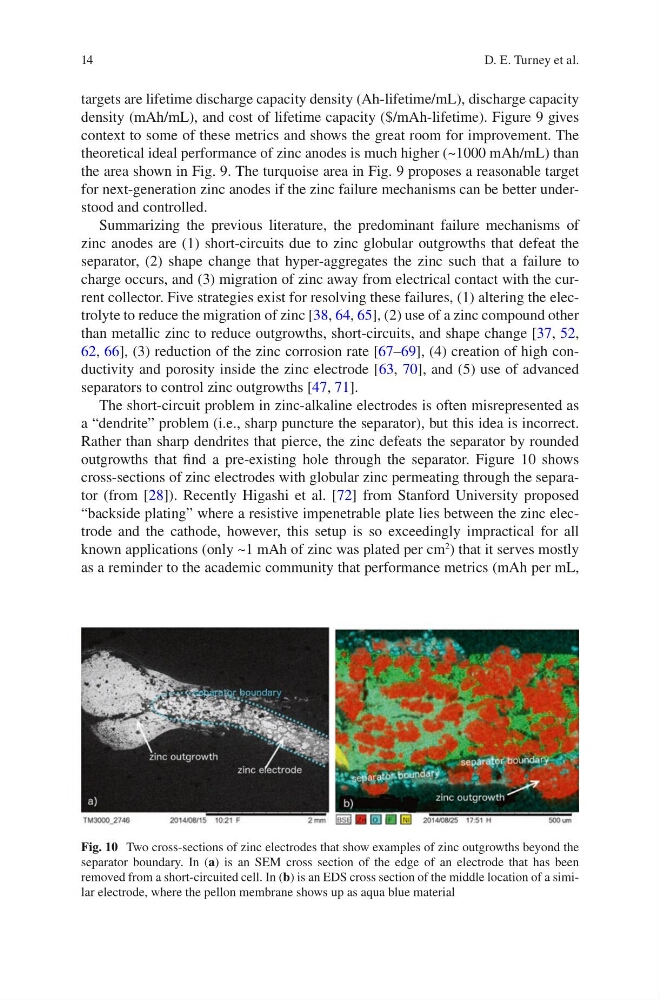
The short-circuit problem in zinc-alkaline electrodes is often misrepresented as
a “dendrite” problem (i.e., sharp puncture the separator), but this idea is incorrect.
Rather than sharp dendrites that pierce, the zinc defeats the separator by rounded
outgrowths that find a pre-existing hole through the separator. Figure 10 shows
cross-sections of zinc electrodes with globular zinc permeating through the separator (from [28]). Recently Higashi et al. [72] from Stanford University proposed
“backside plating” where a resistive impenetrable plate lies between the zinc electrode and the cathode, however, this setup is so exceedingly impractical for all
known applications (only ~1 mAh of zinc was plated per cm
2
) that it serves mostly
as a reminder to the academic community that performance metrics (mAh per mL,
Fig. 10 Two cross-sections of zinc electrodes that show examples of zinc outgrowths beyond the
separator boundary. In (a) is an SEM cross section of the edge of an electrode that has been
removed from a short-circuited cell. In (b) is an EDS cross section of the middle location of a similar electrode, where the pellon membrane shows up as aqua blue material
D. E. Turney et al.
targets are lifetime discharge capacity density (Ah-lifetime/mL), discharge capacity
density (mAh/mL), and cost of lifetime capacity ($/mAh-lifetime). Figure 9 gives
context to some of these metrics and shows the great room for improvement. The
theoretical ideal performance of zinc anodes is much higher (~1000 mAh/mL) than
the area shown in Fig. 9. The turquoise area in Fig. 9 proposes a reasonable target
for next-generation zinc anodes if the zinc failure mechanisms can be better understood and controlled.
Summarizing the previous literature, the predominant failure mechanisms of
zinc anodes are (1) short-circuits due to zinc globular outgrowths that defeat the
separator, (2) shape change that hyper-aggregates the zinc such that a failure to
charge occurs, and (3) migration of zinc away from electrical contact with the current collector. Five strategies exist for resolving these failures, (1) altering the electrolyte to reduce the migration of zinc [38, 64, 65], (2) use of a zinc compound other
than metallic zinc to reduce outgrowths, short-circuits, and shape change [37, 52,
62, 66], (3) reduction of the zinc corrosion rate [67–69], (4) creation of high conductivity and porosity inside the zinc electrode [63, 70], and (5) use of advanced
separators to control zinc outgrowths [47, 71].
The short-circuit problem in zinc-alkaline electrodes is often misrepresented as
a “dendrite” problem (i.e., sharp puncture the separator), but this idea is incorrect.
Rather than sharp dendrites that pierce, the zinc defeats the separator by rounded
outgrowths that find a pre-existing hole through the separator. Figure 10 shows
cross-sections of zinc electrodes with globular zinc permeating through the separator (from [28]). Recently Higashi et al. [72] from Stanford University proposed
“backside plating” where a resistive impenetrable plate lies between the zinc electrode and the cathode, however, this setup is so exceedingly impractical for all
known applications (only ~1 mAh of zinc was plated per cm
2
) that it serves mostly
as a reminder to the academic community that performance metrics (mAh per mL,
Fig. 10 Two cross-sections of zinc electrodes that show examples of zinc outgrowths beyond the
separator boundary. In (a) is an SEM cross section of the edge of an electrode that has been
removed from a short-circuited cell. In (b) is an EDS cross section of the middle location of a similar electrode, where the pellon membrane shows up as aqua blue material
D. E. Turney et al.