

The membranes can be made with different pore-size ranges normally designated
in terms of molecular weight cutoff. Hollow fiber-based membrane elements with
fiber dimensions around 100–150 microns were used for reverse osmosis applications. The use of hollow fine fiber for reverse osmosis is almost discontinued due to
operational and maintenance problems. After the unsatisfactory performance of
polyamide-based hollow fiber elements, cellulose triacetate membrane-based hollow
fine fibers were assessed at some field reverse osmosis plants, but further progress is
not reported. However, hollow fine fiber configuration is the most popular for many
ultrafiltration applications. Comparative characteristics of the membrane module
configurations can be found in Table 8.1.
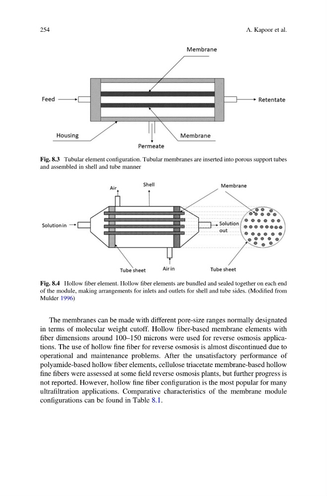
Fig. 8.3 Tubular element configuration. Tubular membranes are inserted into porous support tubes
and assembled in shell and tube manner
Fig. 8.4 Hollow fiber element. Hollow fiber elements are bundled and sealed together on each end
of the module, making arrangements for inlets and outlets for shell and tube sides. (Modified from
Mulder 1996)
254
A. Kapoor et al.
in terms of molecular weight cutoff. Hollow fiber-based membrane elements with
fiber dimensions around 100–150 microns were used for reverse osmosis applications. The use of hollow fine fiber for reverse osmosis is almost discontinued due to
operational and maintenance problems. After the unsatisfactory performance of
polyamide-based hollow fiber elements, cellulose triacetate membrane-based hollow
fine fibers were assessed at some field reverse osmosis plants, but further progress is
not reported. However, hollow fine fiber configuration is the most popular for many
ultrafiltration applications. Comparative characteristics of the membrane module
configurations can be found in Table 8.1.
Fig. 8.3 Tubular element configuration. Tubular membranes are inserted into porous support tubes
and assembled in shell and tube manner
Fig. 8.4 Hollow fiber element. Hollow fiber elements are bundled and sealed together on each end
of the module, making arrangements for inlets and outlets for shell and tube sides. (Modified from
Mulder 1996)
254
A. Kapoor et al.