

surface of the membrane facing the plate surface. The pores provided by design in
the plate allow the feed to be in contact with the membrane. The water permeating
the membrane is transported via the nonwoven fabric to the channels provided on the
plates and then to the collection tube. Many such plates assembled one over the other
constitute a membrane module. The end plates would have only one membrane and a
blinder plate. For example, a 50-plate configuration can hold 98 membrane sheets
with the outer side of the end plates sealed. The sheets can be of any shape, circular,
square, or hexagonal, depending on the pressure plate configuration (Pal 2017).
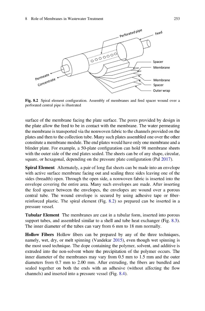
Spiral Element Alternately, a pair of long flat sheets can be made into an envelope
with active surface membrane facing out and sealing three sides leaving one of the
sides (breadth) open. Through the open side, a nonwoven fabric is inserted into the
envelope covering the entire area. Many such envelopes are made. After inserting
the feed spacer between the envelopes, the envelopes are wound over a porous
central tube. The wound envelope is secured by using adhesive tape or fiberreinforced plastic. The spiral element (Fig. 8.2) so prepared can be inserted in a
pressure vessel.
Tubular Element The membranes are cast in a tubular form, inserted into porous
support tubes, and assembled similar to a shell and tube heat exchanger (Fig. 8.3).
The inner diameter of the tubes can vary from 6 mm to 18 mm normally.
Hollow Fibers Hollow fibers can be prepared by any of the three techniques,
namely, wet, dry, or melt spinning (Vandekar 2015), even though wet spinning is
the most used technique. The dope containing the polymer, solvent, and additive is
extruded into the non-solvent where the precipitation of the polymer occurs. The
inner diameter of the membranes may vary from 0.5 mm to 1.5 mm and the outer
diameters from 0.7 mm to 2.00 mm. After extruding, the fibers are bundled and
sealed together on both the ends with an adhesive (without affecting the flow
channels) and inserted into a pressure vessel (Fig. 8.4).
Fig. 8.2 Spiral element configuration. Assembly of membranes and feed spacer wound over a
perforated central pipe is illustrated
8 Role of Membranes in Wastewater Treatment
253
the plate allow the feed to be in contact with the membrane. The water permeating
the membrane is transported via the nonwoven fabric to the channels provided on the
plates and then to the collection tube. Many such plates assembled one over the other
constitute a membrane module. The end plates would have only one membrane and a
blinder plate. For example, a 50-plate configuration can hold 98 membrane sheets
with the outer side of the end plates sealed. The sheets can be of any shape, circular,
square, or hexagonal, depending on the pressure plate configuration (Pal 2017).
Spiral Element Alternately, a pair of long flat sheets can be made into an envelope
with active surface membrane facing out and sealing three sides leaving one of the
sides (breadth) open. Through the open side, a nonwoven fabric is inserted into the
envelope covering the entire area. Many such envelopes are made. After inserting
the feed spacer between the envelopes, the envelopes are wound over a porous
central tube. The wound envelope is secured by using adhesive tape or fiberreinforced plastic. The spiral element (Fig. 8.2) so prepared can be inserted in a
pressure vessel.
Tubular Element The membranes are cast in a tubular form, inserted into porous
support tubes, and assembled similar to a shell and tube heat exchanger (Fig. 8.3).
The inner diameter of the tubes can vary from 6 mm to 18 mm normally.
Hollow Fibers Hollow fibers can be prepared by any of the three techniques,
namely, wet, dry, or melt spinning (Vandekar 2015), even though wet spinning is
the most used technique. The dope containing the polymer, solvent, and additive is
extruded into the non-solvent where the precipitation of the polymer occurs. The
inner diameter of the membranes may vary from 0.5 mm to 1.5 mm and the outer
diameters from 0.7 mm to 2.00 mm. After extruding, the fibers are bundled and
sealed together on both the ends with an adhesive (without affecting the flow
channels) and inserted into a pressure vessel (Fig. 8.4).
Fig. 8.2 Spiral element configuration. Assembly of membranes and feed spacer wound over a
perforated central pipe is illustrated
8 Role of Membranes in Wastewater Treatment
253