

82
N. Sharma and R. Choudhary
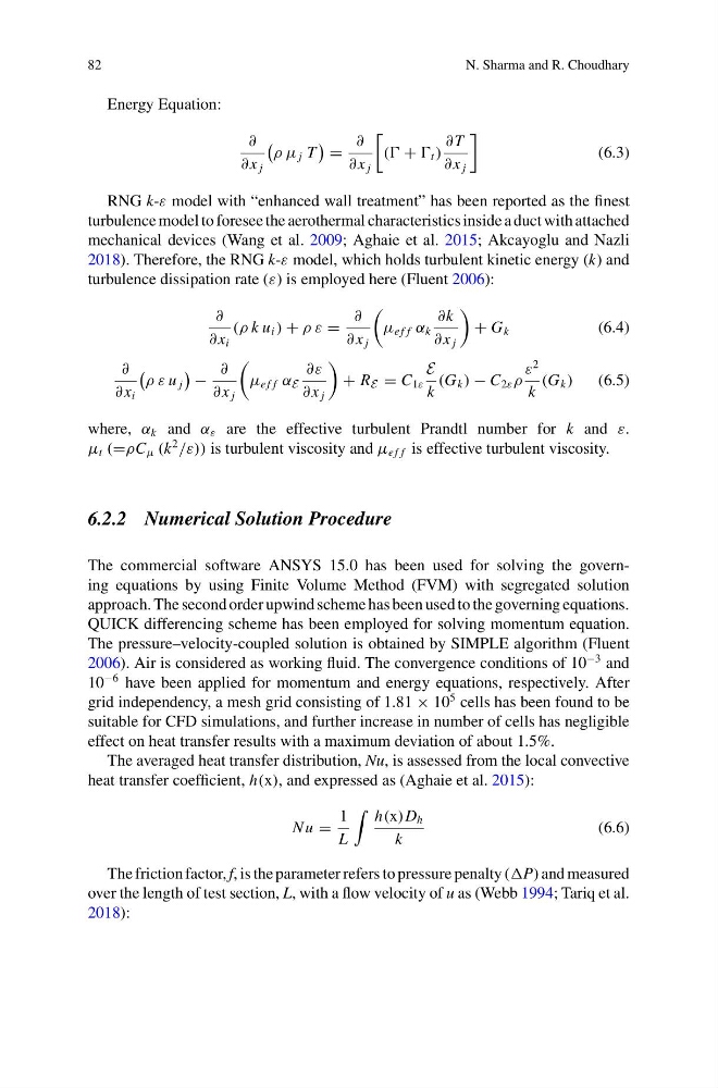
Energy Equation:
∂
∂ x j
ρ μ j T
=
∂
∂ x j
( + t )
∂ T
∂ x j
(6.3)
RNG k-ε model with “enhanced wall treatment” has been reported as the finest
turbulence model to foresee the aerothermal characteristics inside a duct with attached
mechanical devices (Wang et al. 2009; Aghaie et al. 2015; Akcayoglu and Nazli
2018). Therefore, the RNG k-ε model, which holds turbulent kinetic energy (k) and
turbulence dissipation rate (ε) is employed here (Fluent 2006):
∂
∂ x i
(ρ k u i ) + ρ ε =
∂
∂ x j
μ e f f α k
∂k
∂ x j
+ G k
(6.4)
∂
∂ x i
ρ ε u j
−
∂
∂ x j
μ e f f α E
∂ε
∂ x j
+ R E = C 1ε
E
k
(G k ) − C 2ε ρ
ε
2
k
(G k )
(6.5)
where, α k and α ε are the effective turbulent Prandtl number for k and ε.
μ t (=ρC μ (k
2
/ε)) is turbulent viscosity and μ e f f is effective turbulent viscosity.
6.2.2 Numerical Solution Procedure
The commercial software ANSYS 15.0 has been used for solving the governing equations by using Finite Volume Method (FVM) with segregated solution
approach. The second order upwind scheme has been used to the governing equations.
QUICK differencing scheme has been employed for solving momentum equation.
The pressure–velocity-coupled solution is obtained by SIMPLE algorithm (Fluent
2006). Air is considered as working fluid. The convergence conditions of 10
−3 and
10
−6 have been applied for momentum and energy equations, respectively. After
grid independency, a mesh grid consisting of 1.81 × 10
5 cells has been found to be
suitable for CFD simulations, and further increase in number of cells has negligible
effect on heat transfer results with a maximum deviation of about 1.5%.
The averaged heat transfer distribution, Nu, is assessed from the local convective
heat transfer coefficient, h(x), and expressed as (Aghaie et al. 2015):
N u =
1
L
h(x)D h
k
(6.6)
The friction factor, f, is the parameter refers to pressure penalty (P) and measured
over the length of test section, L, with a flow velocity of u as (Webb 1994; Tariq et al.
2018):
N. Sharma and R. Choudhary
Energy Equation:
∂
∂ x j
ρ μ j T
=
∂
∂ x j
( + t )
∂ T
∂ x j
(6.3)
RNG k-ε model with “enhanced wall treatment” has been reported as the finest
turbulence model to foresee the aerothermal characteristics inside a duct with attached
mechanical devices (Wang et al. 2009; Aghaie et al. 2015; Akcayoglu and Nazli
2018). Therefore, the RNG k-ε model, which holds turbulent kinetic energy (k) and
turbulence dissipation rate (ε) is employed here (Fluent 2006):
∂
∂ x i
(ρ k u i ) + ρ ε =
∂
∂ x j
μ e f f α k
∂k
∂ x j
+ G k
(6.4)
∂
∂ x i
ρ ε u j
−
∂
∂ x j
μ e f f α E
∂ε
∂ x j
+ R E = C 1ε
E
k
(G k ) − C 2ε ρ
ε
2
k
(G k )
(6.5)
where, α k and α ε are the effective turbulent Prandtl number for k and ε.
μ t (=ρC μ (k
2
/ε)) is turbulent viscosity and μ e f f is effective turbulent viscosity.
6.2.2 Numerical Solution Procedure
The commercial software ANSYS 15.0 has been used for solving the governing equations by using Finite Volume Method (FVM) with segregated solution
approach. The second order upwind scheme has been used to the governing equations.
QUICK differencing scheme has been employed for solving momentum equation.
The pressure–velocity-coupled solution is obtained by SIMPLE algorithm (Fluent
2006). Air is considered as working fluid. The convergence conditions of 10
−3 and
10
−6 have been applied for momentum and energy equations, respectively. After
grid independency, a mesh grid consisting of 1.81 × 10
5 cells has been found to be
suitable for CFD simulations, and further increase in number of cells has negligible
effect on heat transfer results with a maximum deviation of about 1.5%.
The averaged heat transfer distribution, Nu, is assessed from the local convective
heat transfer coefficient, h(x), and expressed as (Aghaie et al. 2015):
N u =
1
L
h(x)D h
k
(6.6)
The friction factor, f, is the parameter refers to pressure penalty (P) and measured
over the length of test section, L, with a flow velocity of u as (Webb 1994; Tariq et al.
2018):