

6 Multi-objective Performance Optimization of a Ribbed Solar …
81
6.2 Geometric Modeling
A 2-dimensional model of a SAH inserted with periodic ribs, whose front side is
inclined at different angles (45°, 60°, 75°, and 90°), has been developed to understand
the flow and heat transfer features (see Fig. 6.1).
The desired airflow, at atmospheric temperature and pressure, is provided by
selecting suitable Reynolds number (Re = 4000, 8000, 12000 and 16000) in order
to deduce forced convective heat transfer in the duct. The lower ribbed surface is
provided with continuous heat flux of 4000 W/m
2 , while the other sides are adiabatic
in nature. The cross-section of the rib is square, i.e. e = w = 8 mm, while the
duct height (H) and hydraulic diameter (D h ) are 40 and 80 mm (2H). The spacing
between two consecutive ribs is varied as 3e, 6e, 9e, and 12e. Depending upon front
face inclination, the type of rib geometry changes from triangular at inclination angle
of 45° to trapezoidal for inclination angles of 60° and 75°, and square at inclination
angle of 90° (Fig. 6.1).
The computational domain, as shown in Fig. 6.1, is judiciously decided so as to
settle a uniform flow at inlet and fully developed flow at outlet (Aghaie et al. 2015).
Numerical simulations have been carried out with certain assumptions, i.e. the flow is
steady and fully developed turbulent flow, pressure variation and shear forces in wall
normal direction are considered as zero, body forces due to gravity are neglected,
working fluid is considered as an incompressible, and the axial heat conduction in
the fluid is negligible.
6.2.1 Mathematical Modeling
The flow and heat transfer behaviour inside a ribbed SAH are mathematically
described by some governing equations, i.e. continuity, momentum and energy equations, as given below in Cartesian coordinate system (Fluent 2006):
Mass conservation (Continuity equation):
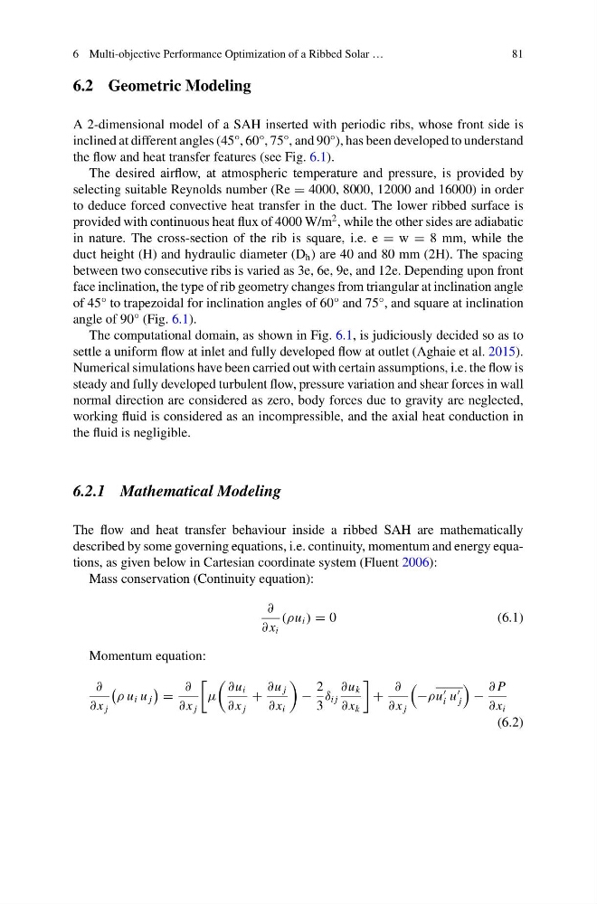
∂
∂ x i
(ρu i ) = 0
(6.1)
Momentum equation:
∂
∂ x j
ρ u i u j
=
∂
∂ x j
μ
∂u i
∂ x j
+
∂u j
∂ x i
−
2
3
δ i j
∂u k
∂ x k
+
∂
∂ x j
−ρu
i u
j
−
∂ P
∂ x i
(6.2)
81
6.2 Geometric Modeling
A 2-dimensional model of a SAH inserted with periodic ribs, whose front side is
inclined at different angles (45°, 60°, 75°, and 90°), has been developed to understand
the flow and heat transfer features (see Fig. 6.1).
The desired airflow, at atmospheric temperature and pressure, is provided by
selecting suitable Reynolds number (Re = 4000, 8000, 12000 and 16000) in order
to deduce forced convective heat transfer in the duct. The lower ribbed surface is
provided with continuous heat flux of 4000 W/m
2 , while the other sides are adiabatic
in nature. The cross-section of the rib is square, i.e. e = w = 8 mm, while the
duct height (H) and hydraulic diameter (D h ) are 40 and 80 mm (2H). The spacing
between two consecutive ribs is varied as 3e, 6e, 9e, and 12e. Depending upon front
face inclination, the type of rib geometry changes from triangular at inclination angle
of 45° to trapezoidal for inclination angles of 60° and 75°, and square at inclination
angle of 90° (Fig. 6.1).
The computational domain, as shown in Fig. 6.1, is judiciously decided so as to
settle a uniform flow at inlet and fully developed flow at outlet (Aghaie et al. 2015).
Numerical simulations have been carried out with certain assumptions, i.e. the flow is
steady and fully developed turbulent flow, pressure variation and shear forces in wall
normal direction are considered as zero, body forces due to gravity are neglected,
working fluid is considered as an incompressible, and the axial heat conduction in
the fluid is negligible.
6.2.1 Mathematical Modeling
The flow and heat transfer behaviour inside a ribbed SAH are mathematically
described by some governing equations, i.e. continuity, momentum and energy equations, as given below in Cartesian coordinate system (Fluent 2006):
Mass conservation (Continuity equation):
∂
∂ x i
(ρu i ) = 0
(6.1)
Momentum equation:
∂
∂ x j
ρ u i u j
=
∂
∂ x j
μ
∂u i
∂ x j
+
∂u j
∂ x i
−
2
3
δ i j
∂u k
∂ x k
+
∂
∂ x j
−ρu
i u
j
−
∂ P
∂ x i
(6.2)