

320
S. Peiris et al.
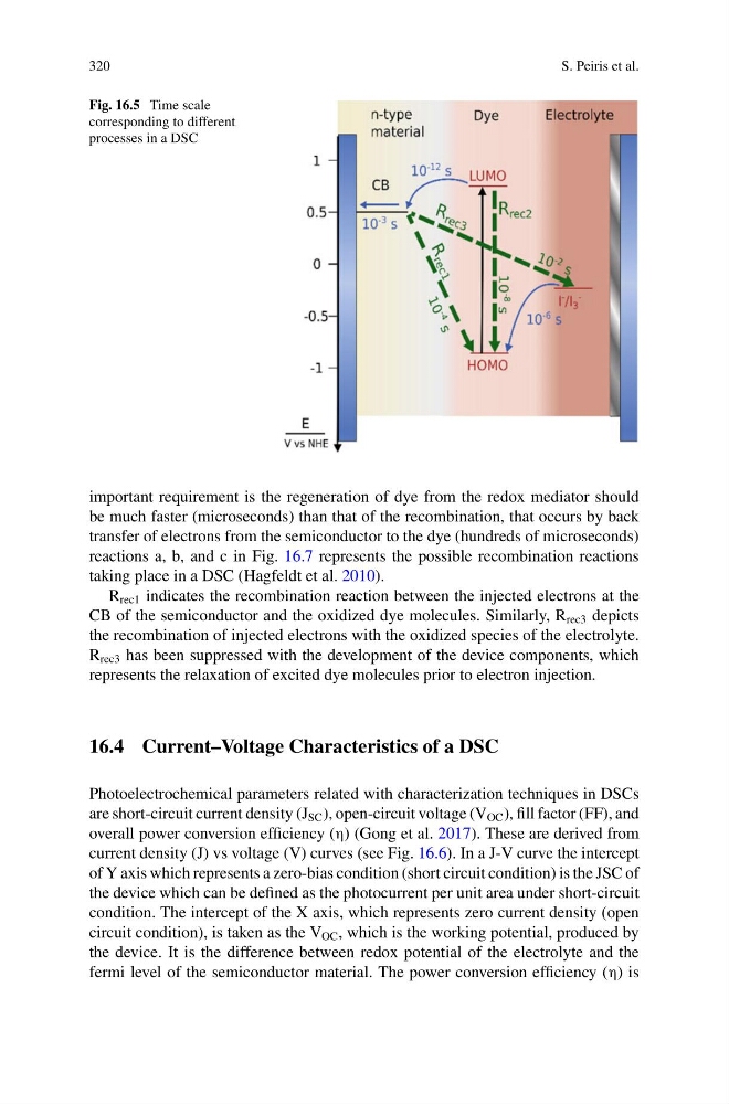
Fig. 16.5 Time scale
corresponding to different
processes in a DSC
important requirement is the regeneration of dye from the redox mediator should
be much faster (microseconds) than that of the recombination, that occurs by back
transfer of electrons from the semiconductor to the dye (hundreds of microseconds)
reactions a, b, and c in Fig. 16.7 represents the possible recombination reactions
taking place in a DSC (Hagfeldt et al. 2010).
R rec1 indicates the recombination reaction between the injected electrons at the
CB of the semiconductor and the oxidized dye molecules. Similarly, R rec3 depicts
the recombination of injected electrons with the oxidized species of the electrolyte.
R rec3 has been suppressed with the development of the device components, which
represents the relaxation of excited dye molecules prior to electron injection.
16.4 Current–Voltage Characteristics of a DSC
Photoelectrochemical parameters related with characterization techniques in DSCs
are short-circuit current density (J SC ), open-circuit voltage (V OC ), fill factor (FF), and
overall power conversion efficiency (η) (Gong et al. 2017). These are derived from
current density (J) vs voltage (V) curves (see Fig. 16.6). In a J-V curve the intercept
of Y axis which represents a zero-bias condition (short circuit condition) is the JSC of
the device which can be defined as the photocurrent per unit area under short-circuit
condition. The intercept of the X axis, which represents zero current density (open
circuit condition), is taken as the V OC , which is the working potential, produced by
the device. It is the difference between redox potential of the electrolyte and the
fermi level of the semiconductor material. The power conversion efficiency (η) is
S. Peiris et al.
Fig. 16.5 Time scale
corresponding to different
processes in a DSC
important requirement is the regeneration of dye from the redox mediator should
be much faster (microseconds) than that of the recombination, that occurs by back
transfer of electrons from the semiconductor to the dye (hundreds of microseconds)
reactions a, b, and c in Fig. 16.7 represents the possible recombination reactions
taking place in a DSC (Hagfeldt et al. 2010).
R rec1 indicates the recombination reaction between the injected electrons at the
CB of the semiconductor and the oxidized dye molecules. Similarly, R rec3 depicts
the recombination of injected electrons with the oxidized species of the electrolyte.
R rec3 has been suppressed with the development of the device components, which
represents the relaxation of excited dye molecules prior to electron injection.
16.4 Current–Voltage Characteristics of a DSC
Photoelectrochemical parameters related with characterization techniques in DSCs
are short-circuit current density (J SC ), open-circuit voltage (V OC ), fill factor (FF), and
overall power conversion efficiency (η) (Gong et al. 2017). These are derived from
current density (J) vs voltage (V) curves (see Fig. 16.6). In a J-V curve the intercept
of Y axis which represents a zero-bias condition (short circuit condition) is the JSC of
the device which can be defined as the photocurrent per unit area under short-circuit
condition. The intercept of the X axis, which represents zero current density (open
circuit condition), is taken as the V OC , which is the working potential, produced by
the device. It is the difference between redox potential of the electrolyte and the
fermi level of the semiconductor material. The power conversion efficiency (η) is