

8 Solar Thermal-Powered Adsorption Chiller
125
through the edges of the collector can be calculated from,
U edge,coll =
(U A) edge,coll
A C
(8.16)
The overall heat transfer coefficient, U L , is essentially the summation of all the
loss coefficients. Adding Eqs. (8.14)–(8.16),
U L = U top,coll + U bot,coll + U edge,coll
(8.17)
Putting the value of U L into Eq. (8.4), one can determine the useful energy gain
Q u , which can be utilized to determine the FPC efficiency η using Eq. (8.3).
8.4 Model Equations of an Evacuated Tube Collector
An evacuated tube collector (ETC) comprises an absorber plate attached to a heat
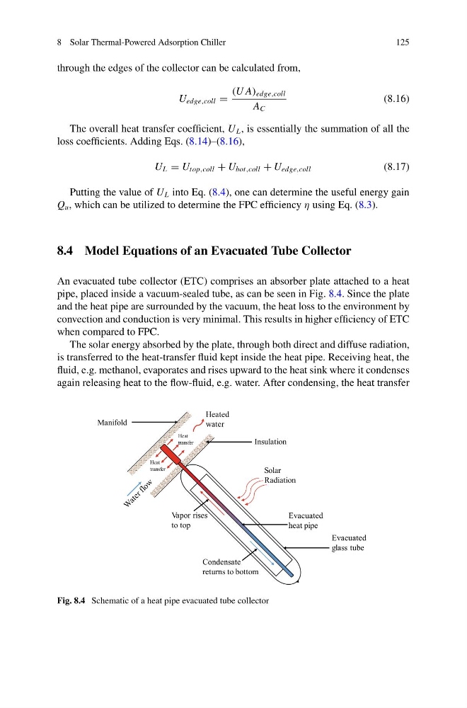
pipe, placed inside a vacuum-sealed tube, as can be seen in Fig. 8.4. Since the plate
and the heat pipe are surrounded by the vacuum, the heat loss to the environment by
convection and conduction is very minimal. This results in higher efficiency of ETC
when compared to FPC.
The solar energy absorbed by the plate, through both direct and diffuse radiation,
is transferred to the heat-transfer fluid kept inside the heat pipe. Receiving heat, the
fluid, e.g. methanol, evaporates and rises upward to the heat sink where it condenses
again releasing heat to the flow-fluid, e.g. water. After condensing, the heat transfer
Solar
Radiation
Evacuated
heat pipe
Evacuated
glass tube
Insulation
Manifold
Heated
water
Condensate
returns to bottom
Vapor rises
to top
Heat
transfer
Heat
transfer
Fig. 8.4 Schematic of a heat pipe evacuated tube collector
125
through the edges of the collector can be calculated from,
U edge,coll =
(U A) edge,coll
A C
(8.16)
The overall heat transfer coefficient, U L , is essentially the summation of all the
loss coefficients. Adding Eqs. (8.14)–(8.16),
U L = U top,coll + U bot,coll + U edge,coll
(8.17)
Putting the value of U L into Eq. (8.4), one can determine the useful energy gain
Q u , which can be utilized to determine the FPC efficiency η using Eq. (8.3).
8.4 Model Equations of an Evacuated Tube Collector
An evacuated tube collector (ETC) comprises an absorber plate attached to a heat
pipe, placed inside a vacuum-sealed tube, as can be seen in Fig. 8.4. Since the plate
and the heat pipe are surrounded by the vacuum, the heat loss to the environment by
convection and conduction is very minimal. This results in higher efficiency of ETC
when compared to FPC.
The solar energy absorbed by the plate, through both direct and diffuse radiation,
is transferred to the heat-transfer fluid kept inside the heat pipe. Receiving heat, the
fluid, e.g. methanol, evaporates and rises upward to the heat sink where it condenses
again releasing heat to the flow-fluid, e.g. water. After condensing, the heat transfer
Solar
Radiation
Evacuated
heat pipe
Evacuated
glass tube
Insulation
Manifold
Heated
water
Condensate
returns to bottom
Vapor rises
to top
Heat
transfer
Heat
transfer
Fig. 8.4 Schematic of a heat pipe evacuated tube collector