

126
M. Muttakin et al.
fluid returns to the collector for receiving heat from the absorbed solar energy again.
Thus it undergoes an evaporating—condensing cycle.
8.4.1 Efficiency of an ETC
The efficiency and useful energy gain of such a collector can be obtained using the
same equations as used for FPC, i.e. Eqs. (8.3) and (8.4).
η =
Q u
Q T
=
Q u
G A c
Q u = A c [G S − U L (T c − T a )]
Also from Eq. (8.5), we know, G S = G(τ α) eff . For evacuated tube collectors,
the overall incidence angle modifier K τ α is equal to the product of incidence angle
modifier in transverse plane K t and that in longitudinal plane K l ,
K τ α = K t .K l =
(τ α) e f f
(τ α) n
In order to determine the efficiency and useful energy gain, it is important to know
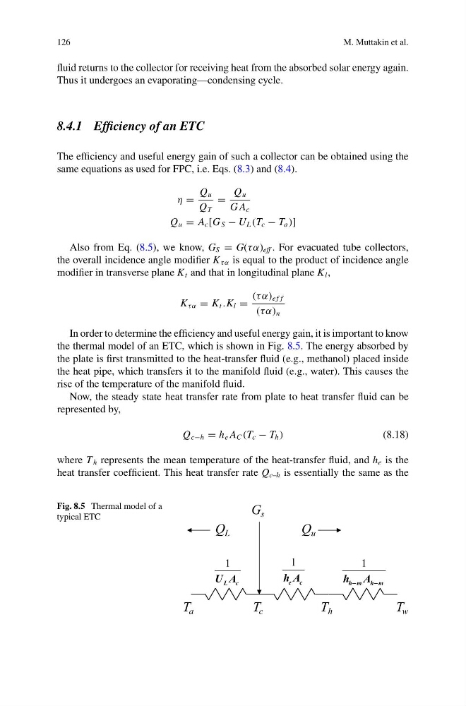
the thermal model of an ETC, which is shown in Fig. 8.5. The energy absorbed by
the plate is first transmitted to the heat-transfer fluid (e.g., methanol) placed inside
the heat pipe, which transfers it to the manifold fluid (e.g., water). This causes the
rise of the temperature of the manifold fluid.
Now, the steady state heat transfer rate from plate to heat transfer fluid can be
represented by,
Q c−h = h e A C (T c − T h )
(8.18)
where T h represents the mean temperature of the heat-transfer fluid, and h e is the
heat transfer coefficient. This heat transfer rate Q c–h is essentially the same as the
Fig. 8.5 Thermal model of a
typical ETC
G s
Q u
T a
T c
Q L
T h
T w
1
L c
U A
1
e c
h A
1
h m h m
h A
−
−
M. Muttakin et al.
fluid returns to the collector for receiving heat from the absorbed solar energy again.
Thus it undergoes an evaporating—condensing cycle.
8.4.1 Efficiency of an ETC
The efficiency and useful energy gain of such a collector can be obtained using the
same equations as used for FPC, i.e. Eqs. (8.3) and (8.4).
η =
Q u
Q T
=
Q u
G A c
Q u = A c [G S − U L (T c − T a )]
Also from Eq. (8.5), we know, G S = G(τ α) eff . For evacuated tube collectors,
the overall incidence angle modifier K τ α is equal to the product of incidence angle
modifier in transverse plane K t and that in longitudinal plane K l ,
K τ α = K t .K l =
(τ α) e f f
(τ α) n
In order to determine the efficiency and useful energy gain, it is important to know
the thermal model of an ETC, which is shown in Fig. 8.5. The energy absorbed by
the plate is first transmitted to the heat-transfer fluid (e.g., methanol) placed inside
the heat pipe, which transfers it to the manifold fluid (e.g., water). This causes the
rise of the temperature of the manifold fluid.
Now, the steady state heat transfer rate from plate to heat transfer fluid can be
represented by,
Q c−h = h e A C (T c − T h )
(8.18)
where T h represents the mean temperature of the heat-transfer fluid, and h e is the
heat transfer coefficient. This heat transfer rate Q c–h is essentially the same as the
Fig. 8.5 Thermal model of a
typical ETC
G s
Q u
T a
T c
Q L
T h
T w
1
L c
U A
1
e c
h A
1
h m h m
h A
−
−